Direct2D 和 GDI 互作性概觀
本主題說明如何使用 Direct2D 和 GDI。 有兩種方式可將 Direct2D 與 GDI 結合:您可以將 GDI 內容寫入 Direct2D GDI 相容的轉譯目標,或將 Direct2D 內容寫入至 GDI 裝置內容 (DC)。
本主題包含下列各節。
- 必要條件
- 將 Direct2D 內容繪製至 GDI 裝置內容環境
- ID2D1DCRenderTargets、GDI 轉換和 Windows 的由右至左語言組建
- 將 GDI 內容繪製到 Direct2D GDI-Compatible 呈現目標
- 相關主題
先決條件
此概觀假設您已熟悉基本的 Direct2D 繪圖作業。 如需教學課程,請參閱 建立簡單的 Direct2D 應用程式。 它也假設您已熟悉 GDI 繪圖作業。
將 Direct2D 內容繪製至 GDI 裝置上下文
若要將 Direct2D 內容繪製至 GDI DC,請使用 ID2D1DCRenderTarget。 若要建立 DC 轉譯目標,您可以使用 ID2D1Factory::CreateDCRenderTarget 方法。 此方法會採用兩個參數。
第一個參數,D2D1_RENDER_TARGET_PROPERTIES 結構,指定渲染、遠端處理、DPI、像素格式和使用資訊。 若要讓 DC 轉譯目標能夠使用 GDI,請將 DXGI 格式設定為 DXGI_FORMAT_B8G8R8A8_UNORM,並將 Alpha 模式設定為 D2D1_ALPHA_MODE_PREMULTIPLIED 或 D2D1_ALPHA_MODE_IGNORE。
第二個參數是接收 DC 渲染目標參考之指標的位址。
下列程式碼會建立一個 DC 繪製目標。
// Create a DC render target.
D2D1_RENDER_TARGET_PROPERTIES props = D2D1::RenderTargetProperties(
    D2D1_RENDER_TARGET_TYPE_DEFAULT,
    D2D1::PixelFormat(
        DXGI_FORMAT_B8G8R8A8_UNORM,
        D2D1_ALPHA_MODE_IGNORE),
    0,
    0,
    D2D1_RENDER_TARGET_USAGE_NONE,
    D2D1_FEATURE_LEVEL_DEFAULT
    );

hr = m_pD2DFactory->CreateDCRenderTarget(&props, &m_pDCRT);
在上述程式代碼中,m_pD2DFactory 是 ID2D1Factory的指標,而 m_pDCRT 是 ID2D1DCRenderTarget的指標。
在您使用 DC 渲染目標前,必須先使用其 BindDC 方法將其與 GDI DC 綁定。 使用不同的 DC 時或欲繪製的區域大小改變時,您都會這麼做。
BindDC 方法會採用兩個參數,hDC 和 pSubRect。 hDC 參數提供接收轉譯目標輸出之裝置內容的句柄。 pSubRect 參數是一個矩形,用來描述裝置環境中呈現內容的區域。 DC 轉譯目標會在其大小改變時,更新其大小,以符合 pSubRect中所述的裝置內容區域。
下列程式代碼會將DC系結至DC轉譯目標。
HRESULT DemoApp::OnRender(const PAINTSTRUCT &ps)
{


// Get the dimensions of the client drawing area.
GetClientRect(m_hwnd, &rc);
| C++ |
|---|
|
將DC呈現目標與DC建立關聯後,您即可使用它來進行繪圖。 下列程式代碼會使用DC繪製 Direct2D 和 GDI 內容。
HRESULT DemoApp::OnRender(const PAINTSTRUCT &ps)
{
HRESULT hr;
RECT rc;
// Get the dimensions of the client drawing area.
GetClientRect(m_hwnd, &rc);
//
// Draw the pie chart with Direct2D.
//
// Create the DC render target.
hr = CreateDeviceResources();
if (SUCCEEDED(hr))
{
// Bind the DC to the DC render target.
hr = m_pDCRT->BindDC(ps.hdc, &rc);
m_pDCRT->BeginDraw();
m_pDCRT->SetTransform(D2D1::Matrix3x2F::Identity());
m_pDCRT->Clear(D2D1::ColorF(D2D1::ColorF::White));
m_pDCRT->DrawEllipse(
D2D1::Ellipse(
D2D1::Point2F(150.0f, 150.0f),
100.0f,
100.0f),
m_pBlackBrush,
3.0
);
m_pDCRT->DrawLine(
D2D1::Point2F(150.0f, 150.0f),
D2D1::Point2F(
(150.0f + 100.0f * 0.15425f),
(150.0f - 100.0f * 0.988f)),
m_pBlackBrush,
3.0
);
m_pDCRT->DrawLine(
D2D1::Point2F(150.0f, 150.0f),
D2D1::Point2F(
(150.0f + 100.0f * 0.525f),
(150.0f + 100.0f * 0.8509f)),
m_pBlackBrush,
3.0
);
m_pDCRT->DrawLine(
D2D1::Point2F(150.0f, 150.0f),
D2D1::Point2F(
(150.0f - 100.0f * 0.988f),
(150.0f - 100.0f * 0.15425f)),
m_pBlackBrush,
3.0
);
hr = m_pDCRT->EndDraw();
if (SUCCEEDED(hr))
{
//
// Draw the pie chart with GDI.
//
// Save the original object.
HGDIOBJ original = NULL;
original = SelectObject(
ps.hdc,
GetStockObject(DC_PEN)
);
HPEN blackPen = CreatePen(PS_SOLID, 3, 0);
SelectObject(ps.hdc, blackPen);
Ellipse(ps.hdc, 300, 50, 500, 250);
POINT pntArray1[2];
pntArray1[0].x = 400;
pntArray1[0].y = 150;
pntArray1[1].x = static_cast<LONG>(400 + 100 * 0.15425);
pntArray1[1].y = static_cast<LONG>(150 - 100 * 0.9885);
POINT pntArray2[2];
pntArray2[0].x = 400;
pntArray2[0].y = 150;
pntArray2[1].x = static_cast<LONG>(400 + 100 * 0.525);
pntArray2[1].y = static_cast<LONG>(150 + 100 * 0.8509);
POINT pntArray3[2];
pntArray3[0].x = 400;
pntArray3[0].y = 150;
pntArray3[1].x = static_cast<LONG>(400 - 100 * 0.988);
pntArray3[1].y = static_cast<LONG>(150 - 100 * 0.15425);
Polyline(ps.hdc, pntArray1, 2);
Polyline(ps.hdc, pntArray2, 2);
Polyline(ps.hdc, pntArray3, 2);
DeleteObject(blackPen);
// Restore the original object.
SelectObject(ps.hdc, original);
}
}
if (hr == D2DERR_RECREATE_TARGET)
{
hr = S_OK;
DiscardDeviceResources();
}
return hr;
}
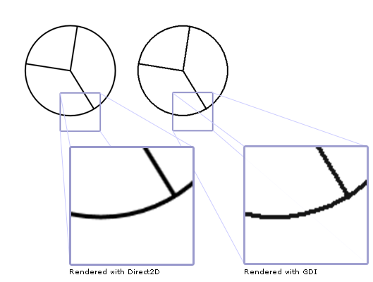
此程式碼會產生如圖所示的輸出(附註已被添加以突出 Direct2D 和 GDI 渲染之間的差異)。
ID2D1DCRenderTargets、GDI 轉換和 Windows 的從右至左語言組建
當您使用 ID2D1DCRenderTarget時,它會將 Direct2D 內容轉譯為內部點陣圖,然後使用 GDI 將點陣圖轉譯為 DC。
GDI 可以套用 GDI 轉換(透過 SetWorldTransform 方法)或其他效果至轉譯目標所使用的相同 DC,在此情況下,GDI 會轉換 Direct2D 所產生的位圖。 使用 GDI 轉換來轉換 Direct2D 內容可能會降低輸出的視覺質量,因為您正在轉換已計算反鋸齒和子圖元定位的點陣圖。
例如,假設您使用渲染目標繪製包含文字和反鋸齒幾何的場景。 如果您使用 GDI 轉換將縮放變換套用至 DC,並將場景放大至 10 倍大小,您會看到像素化和鋸齒狀邊緣。 (不過,如果您使用 Direct2D 套用類似的轉換,則場景的視覺品質不會降低。
在某些情況下,GDI 執行的附加處理可能會降低 Direct2D 內容的質量,而這可能並不明顯。 例如,在 Windows 的由右至左 (RTL) 組建上,當 GDI 將它複製到目的地時,ID2D1DCRenderTarget 所轉譯的內容可能會水準反轉。 內容是否真的反轉取決於直流電源(DC)的當前設定。
視所呈現的內容類型而定,您可能會想要防止反轉。 如果 Direct2D 內容包含 ClearType 文字,此反轉會降低文字的品質。
您可以使用 SetLayout GDI 函式來控制 RTL 轉譯行為。 若要防止鏡像,請呼叫 SetLayout GDI 函式,並將 LAYOUT_BITMAPORIENTATIONPRESERVED 指定為第二個參數的唯一值(請勿與 LAYOUT_RTL合併),如下列範例所示:
SetLayout(m_hwnd, LAYOUT_BITMAPORIENTATIONPRESERVED);
將 GDI 內容繪製至 Direct2D GDI-Compatible 渲染目標
上一節說明如何將 Direct2D 內容寫入 GDI DC。 您也可以將 GDI 內容寫入相容 GDI 的 Direct2D 渲染目標。 這種方法適用於主要使用 Direct2D 轉譯,但具有擴充性模型或其他需要使用 GDI 轉譯的舊版內容的應用程式。
若要將 GDI 內容轉譯為 Direct2D 的 GDI 相容轉譯目標,請使用 ID2D1GdiInteropRenderTarget,這將提供對可接受 GDI 繪圖呼叫的裝置內容的存取權。 不同於其他介面,不會直接建立 ID2D1GdiInteropRenderTarget 物件。 改為使用現有轉譯目標實例的 QueryInterface 方法。 下列程式代碼示範如何執行這項作:
        D2D1_RENDER_TARGET_PROPERTIES rtProps = D2D1::RenderTargetProperties();
        rtProps.usage =  D2D1_RENDER_TARGET_USAGE_GDI_COMPATIBLE;

        // Create a GDI compatible Hwnd render target.
        hr = m_pD2DFactory->CreateHwndRenderTarget(
            rtProps,
            D2D1::HwndRenderTargetProperties(m_hwnd, size),
            &m_pRenderTarget
            );


        if (SUCCEEDED(hr))
        {
            hr = m_pRenderTarget->QueryInterface(__uuidof(ID2D1GdiInteropRenderTarget), (void**)&m_pGDIRT);
        }
在上述程式代碼中,m_pD2DFactory 是 ID2D1Factory的指標,而 m_pGDIRT 是 ID2D1GdiInteropRenderTarget的指標。
請注意,當建立與 GDI 相容的 Hwnd 轉譯目標時,會指定D2D1_RENDER_TARGET_USAGE_GDI_COMPATIBLE 旗標。 如果需要像素格式,請使用 DXGI_FORMAT_B8G8R8A8_UNORM。 如果需要 Alpha 模式,請使用 D2D1_ALPHA_MODE_PREMULTIPLIED 或 D2D1_ALPHA_MODE_IGNORE。
請注意,QueryInterface 方法一律會成功。 若要測試 ID2D1GdiInteropRenderTarget 介面的方法是否適用於指定的轉譯目標,請建立指定 GDI 相容性和適當圖元格式的 D2D1_RENDER_TARGET_PROPERTIES,然後呼叫轉譯目標的 IsSupported 方法來查看轉譯目標是否與 GDI 相容。
以下範例展示如何將餅圖(包含 GDI 內容)繪製到 Hwnd GDI 相容的渲染目標。
        HDC hDC = NULL;
        hr = m_pGDIRT->GetDC(D2D1_DC_INITIALIZE_MODE_COPY, &hDC);

        if (SUCCEEDED(hr))
        {
            // Draw the pie chart to the GDI render target associated with the Hwnd render target.
            HGDIOBJ original = NULL;
            original = SelectObject(
                hDC,
                GetStockObject(DC_PEN)
                );

            HPEN blackPen = CreatePen(PS_SOLID, 3, 0);
            SelectObject(hDC, blackPen);

            Ellipse(hDC, 300, 50, 500, 250);

            POINT pntArray1[2];
            pntArray1[0].x = 400;
            pntArray1[0].y = 150;
            pntArray1[1].x = static_cast<LONG>(400 + 100 * 0.15425);
            pntArray1[1].y = static_cast<LONG>(150 - 100 * 0.9885);

            POINT pntArray2[2];
            pntArray2[0].x = 400;
            pntArray2[0].y = 150;
            pntArray2[1].x = static_cast<LONG>(400 + 100 * 0.525);
            pntArray2[1].y = static_cast<LONG>(150 + 100 * 0.8509);

            POINT pntArray3[2];
            pntArray3[0].x = 400;
            pntArray3[0].y = 150;
            pntArray3[1].x = static_cast<LONG>(400 - 100 * 0.988);
            pntArray3[1].y = static_cast<LONG>(150 - 100 * 0.15425);

            Polyline(hDC, pntArray1, 2);
            Polyline(hDC, pntArray2, 2);
            Polyline(hDC, pntArray3, 2);

            DeleteObject(blackPen);

            // Restore the original object.
            SelectObject(hDC, original);

            m_pGDIRT->ReleaseDC(NULL);
        }
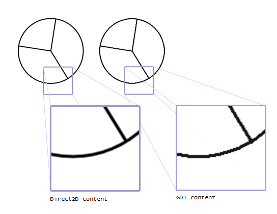
程式碼會輸出圖表,如下圖所示,並使用註解來強調繪製質量的差異。 右餅圖 (GDI 內容) 的轉譯質量低於左餅圖 (Direct2D 內容)。 這是因為 Direct2D 能夠使用抗鋸齒進行繪製
相關主題