圖形物件的狀態
Graphics類別是 Windows GDI+的核心。 若要繪製任何專案,您可以建立Graphics物件、設定其屬性,以及呼叫其方法, ( DrawLine、DrawImage、DrawString等) 。
下列範例會建構Graphics物件和Pen物件,然後呼叫Graphics物件的Graphics::D rawRectangle方法:
HDC          hdc;
PAINTSTRUCT  ps;

hdc = BeginPaint(hWnd, &ps);
{
   Graphics graphics(hdc);
   Pen pen(Color(255, 0, 0, 255));  // opaque blue
   graphics.DrawRectangle(&pen, 10, 10, 200, 100);
}
EndPaint(hWnd, &ps);
在上述程式碼中, BeginPaint 方法會傳回裝置內容的控制碼,且該控制碼會傳遞至 Graphics 建構函式 。 裝置內容是由 Windows) 維護的結構 (,可保存所使用之特定顯示裝置的相關資訊。
圖形狀態
Graphics物件不只是提供繪圖方法,例如DrawLine和DrawRectangle。 Graphics物件也會維護圖形狀態,這可以分成下列類別:
- 裝置內容的連結
- 品質設定
- 轉換
- 裁剪區域
裝置內容
身為應用程式程式設計人員,您不需要考慮 Graphics 物件與其裝置內容之間的互動。 此互動是由 GDI+ 在幕後處理。
品質設定
Graphics物件有數個屬性,會影響在螢幕上繪製的專案品質。 您可以藉由呼叫 get 和 set 方法來檢視及操作這些屬性。 例如,您可以呼叫 Graphics::SetTextRenderingHint 方法,以指定在套用至文字的任何) 時, (的反鋸齒類型。 影響品質的其他集合方法是Graphics::SetSmoothingMode、Graphics::SetCompositingMode、Graphics::SetCompositingQuality和Graphics::SetInterpolationMode。
下列範例會繪製兩個省略號,其中一個平滑模式設定為 SmoothingModeAntiAlias ,另一個將 smoothing 模式設定為 SmoothingModeHighSpeed:
Graphics graphics(hdc);
Pen pen(Color(255, 0, 255, 0));  // opaque green

graphics.SetSmoothingMode(SmoothingModeAntiAlias);
graphics.DrawEllipse(&pen, 0, 0, 200, 100);
graphics.SetSmoothingMode(SmoothingModeHighSpeed);
graphics.DrawEllipse(&pen, 0, 150, 200, 100);
轉換
Graphics物件會維護兩個轉換 (世界和頁面) ,這些轉換會套用至該Graphics物件所繪製的所有專案。 任何相依轉換都可以儲存在世界轉換中。 Affine 轉換包括縮放、旋轉、反映、扭曲和翻譯。 頁面轉換可用於縮放,以及變更單位 (,例如圖元到英吋) 。 如需轉換的詳細資訊,請參閱 座標系統和轉換。
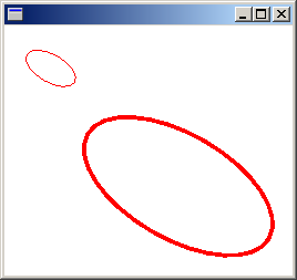
下列範例會設定 Graphics 物件的世界和頁面轉換。 世界轉換設定為 30 度旋轉。 頁面轉換已設定,以便將傳遞至第二個 Graphics::D rawEllipse 的座標視為公釐,而不是圖元。 程式碼會對 Graphics::D rawEllipse 方法進行兩個相同的呼叫。 世界轉換會套用至第一個 Graphics::D rawEllipse 呼叫,而轉換 (世界和頁面) 都會套用至第二個 Graphics::D rawEllipse 呼叫。
Graphics graphics(hdc);
Pen pen(Color(255, 255, 0, 0));

graphics.ResetTransform();
graphics.RotateTransform(30.0f);            // World transformation
graphics.DrawEllipse(&pen, 30, 0, 50, 25);
graphics.SetPageUnit(UnitMillimeter);       // Page transformation
graphics.DrawEllipse(&pen, 30, 0, 50, 25);
下圖顯示兩個省略號。 請注意,30 度旋轉與座標系統的原點有關, (工作區左上角) ,而不是橢圓形的中心。 另請注意,1 的畫筆寬度表示第一個橢圓形的 1 圖元,而第二個橢圓形則表示 1 公釐。

裁剪區域
Graphics物件會維護裁剪區域,以套用至該Graphics物件所繪製的所有專案。 您可以呼叫 SetClip 方法來設定裁剪區域。
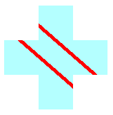
下列範例會藉由形成兩個矩形的聯集來建立加型區域。 該區域會指定為 Graphics 物件的裁剪區域。 然後,程式碼會繪製限制為裁剪區域內部的兩行。
Graphics graphics(hdc);
Pen pen(Color(255, 255, 0, 0), 5); // opaque red, width 5
SolidBrush brush(Color(255, 180, 255, 255)); // opaque aqua
// Create a plus-shaped region by forming the union of two rectangles.
Region region(Rect(50, 0, 50, 150));
region.Union(Rect(0, 50, 150, 50));
graphics.FillRegion(&brush, ®ion);
// Set the clipping region.
graphics.SetClip(®ion);
// Draw two clipped lines.
graphics.DrawLine(&pen, 0, 30, 150, 160);
graphics.DrawLine(&pen, 40, 20, 190, 150);
下圖顯示裁剪的線條。
