如何繪製和填滿複雜圖形
Direct2D 提供 ID2D1PathGeometry介面,用來描述可包含曲線、弧線和線條的複雜圖形。 本主題描述如何定義和轉譯路徑幾何。
若要定義路徑幾何,請先使用 ID2D1Factory::CreatePathGeometry 方法來建立路徑幾何,然後使用路徑幾何的 Open 方法來擷取 ID2D1GeometrySink。 接著,您可以藉由呼叫接收的各種 Add 方法,來新增線條、曲線和弧線。
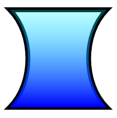
下列範例會建立 ID2D1PathGeometry、擷取接收,並使用它來定義沙漏形狀。
ID2D1GeometrySink *pSink = NULL;

// Create a path geometry.
if (SUCCEEDED(hr))
{
    hr = m_pD2DFactory->CreatePathGeometry(&m_pPathGeometry);

    if (SUCCEEDED(hr))
    {
        // Write to the path geometry using the geometry sink.
        hr = m_pPathGeometry->Open(&pSink);

        if (SUCCEEDED(hr))
        {
            pSink->BeginFigure(
                D2D1::Point2F(0, 0),
                D2D1_FIGURE_BEGIN_FILLED
                );

            pSink->AddLine(D2D1::Point2F(200, 0));

            pSink->AddBezier(
                D2D1::BezierSegment(
                    D2D1::Point2F(150, 50),
                    D2D1::Point2F(150, 150),
                    D2D1::Point2F(200, 200))
                );

            pSink->AddLine(D2D1::Point2F(0, 200));

            pSink->AddBezier(
                D2D1::BezierSegment(
                    D2D1::Point2F(50, 150),
                    D2D1::Point2F(50, 50),
                    D2D1::Point2F(0, 0))
                );

            pSink->EndFigure(D2D1_FIGURE_END_CLOSED);

            hr = pSink->Close();
        }
        SafeRelease(&pSink);
    }
}
請注意, ID2D1PathGeometry 是與裝置無關的資源,因此可以建立一次,並保留應用程式存留期。 (如需不同資源類型的詳細資訊,請參閱 資源概觀.)
下一個範例會建立兩個筆刷,用來繪製路徑幾何的外框和填滿。
if (SUCCEEDED(hr))
{
    // Create a black brush.
    hr = m_pRenderTarget->CreateSolidColorBrush(
        D2D1::ColorF(D2D1::ColorF::Black),
        &m_pBlackBrush
        );
}

if (SUCCEEDED(hr))
{
    // Create a linear gradient.
    static const D2D1_GRADIENT_STOP stops[] =
    {
        {   0.f,  { 0.f, 1.f, 1.f, 0.25f }  },
        {   1.f,  { 0.f, 0.f, 1.f, 1.f }  },
    };

    hr = m_pRenderTarget->CreateGradientStopCollection(
        stops,
        ARRAYSIZE(stops),
        &pGradientStops
        );

    if (SUCCEEDED(hr))
    {
        hr = m_pRenderTarget->CreateLinearGradientBrush(
            D2D1::LinearGradientBrushProperties(
                D2D1::Point2F(100, 0),
                D2D1::Point2F(100, 200)),
            D2D1::BrushProperties(),
            pGradientStops,
            &m_pLGBrush
            );
    }

    SafeRelease(&pGradientStops);
}
最後一個範例會使用 DrawGeometry 和 FillGeometry 方法來繪製幾何的外框和內部。 此範例會產生下圖所示的輸出。

void DemoApp::RenderGeometryExample()
{
    // Translate subsequent drawings by 20 device-independent pixels.
    m_pRenderTarget->SetTransform(
        D2D1::Matrix3x2F::Translation(20.f, 20.f)
        );

    // Draw the hour glass geometry at the upper left corner of the client area.
    m_pRenderTarget->DrawGeometry(m_pPathGeometry, m_pBlackBrush, 10.f);
    m_pRenderTarget->FillGeometry(m_pPathGeometry, m_pLGBrush);
}
此範例已省略程式碼。 如需幾何的詳細資訊,請參閱 幾何概觀。