轉換轉譯架構
摘要
- 第 1 部分:初始化 Direct3D 11
- 第 2 部分:轉換轉譯架構
- 第 3 部分:移植遊戲迴圈
說明如何將簡單的轉譯架構從 Direct3D 9 轉換為 Direct3D 11,包括:如何移植幾何緩衝區、如何編譯和載入 HLSL 著色器程式,以及如何在 Direct3D 11 中實作轉譯鏈結。 《將簡單的 Direct3D 9 應用程式移植到 DirectX 11 和通用 Windows 平台 (UWP)》逐步解說的第 2 部分。
將效果轉換為 HLSL 著色器
下列範例是簡單的 D3DX 技術 (針對舊版效果 API 撰寫),用於硬體頂點轉換和傳遞色彩資料。
Direct3D 9 著色器程式碼
// Global variables
matrix g_mWorld;        // world matrix for object
matrix g_View;          // view matrix
matrix g_Projection;    // projection matrix

// Shader pipeline structures
struct VS_OUTPUT
{
    float4 Position   : POSITION;   // vertex position
    float4 Color      : COLOR0;     // vertex diffuse color
};

struct PS_OUTPUT
{
    float4 RGBColor : COLOR0;  // Pixel color
};

// Vertex shader
VS_OUTPUT RenderSceneVS(float3 vPos : POSITION,
                        float3 vColor : COLOR0)
{
    VS_OUTPUT Output;

    float4 pos = float4(vPos, 1.0f);

    // Transform the position from object space to homogeneous projection space
    pos = mul(pos, g_mWorld);
    pos = mul(pos, g_View);
    pos = mul(pos, g_Projection);

    Output.Position = pos;

    // Just pass through the color data
    Output.Color = float4(vColor, 1.0f);

    return Output;
}

// Pixel shader
PS_OUTPUT RenderScenePS(VS_OUTPUT In)
{
    PS_OUTPUT Output;

    Output.RGBColor = In.Color;

    return Output;
}

// Technique
technique RenderSceneSimple
{
    pass P0
    {
        VertexShader = compile vs_2_0 RenderSceneVS();
        PixelShader  = compile ps_2_0 RenderScenePS();
    }
}
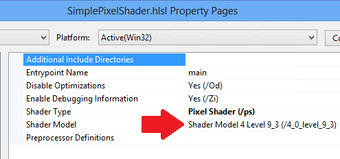
在 Direct3D 11 中,我們仍可使用 HLSL 著色器。 我們將每個著色器放在各自的 HLSL 檔案中,讓 Visual Studio 編譯至個別檔案。稍後,我們就可將其載入為不同的 Direct3D 資源。 我們將目標層級設為 Shader Model 4 Level 9_1 (/4_0_level_9_1),因為這些著色器是專為 DirectX 9.1 GPU 而撰寫。
定義輸入配置時,我們會確保其代表的資料結構,與在系統記憶體和 GPU 記憶體中儲存各頂點資料的資料結構相同。 同樣地,頂點著色器的輸出應符合輸入像素著色器時所用的結構。 這些規則與使用 C++ 語言在函式之間傳遞資料的規則不同;您可以在結構結尾省略未使用的變數。 但是順序無法重新排列,且您也無法略過數據結構中間的內容。
注意相較於 Direct3D 11 中的規則,Direct3D 9 中將頂點著色器繫結至像素著色器的規則更寬鬆。 Direct3D 9 的排列有彈性,但效率不佳。
HLSL 檔案的著色器語意可能會使用較舊的語法,例如 COLOR,而不是SV_TARGET。 若是如此,您必須啟用 HLSL 相容性模式 (/Gec 編譯器選項) 或將著色器語意更新為目前的語法。 此範例中的頂點著色器已更新為目前的語法。
以下是硬體轉換頂點著色器,這次是在其檔案中定義。
注意必須有頂點著色器,才能輸出 SV_POSITION 系統值語意。 此語意會將頂點位置資料解析為座標值,其中的 x 介於 -1 到 1 之間,y 介於 -1 到 1 之間,z 是除以原始同質座標 w 值 (z/w),而 w 則是 1 除以原始 w 值 (1/w)。
HLSL 頂點著色器 (功能層級 9.1)
cbuffer ModelViewProjectionConstantBuffer : register(b0)
{
    matrix mWorld;       // world matrix for object
    matrix View;        // view matrix
    matrix Projection;  // projection matrix
};

struct VS_INPUT
{
    float3 vPos   : POSITION;
    float3 vColor : COLOR0;
};

struct VS_OUTPUT
{
    float4 Position : SV_POSITION; // Vertex shaders must output SV_POSITION
    float4 Color    : COLOR0;
};

VS_OUTPUT main(VS_INPUT input) // main is the default function name
{
    VS_OUTPUT Output;

    float4 pos = float4(input.vPos, 1.0f);

    // Transform the position from object space to homogeneous projection space
    pos = mul(pos, mWorld);
    pos = mul(pos, View);
    pos = mul(pos, Projection);
    Output.Position = pos;

    // Just pass through the color data
    Output.Color = float4(input.vColor, 1.0f);

    return Output;
}
這是傳遞像素著色器所需的所有項目。 雖然我們稱之為傳遞,但該程序實際上會針對每個像素取得已校正透視的插補色彩資料。 請注意,SV_TARGET系統值語意會套用至 API 要求的像素著色器輸出色彩值。
注意著色器層級 9_x 像素著色器無法從 SV_POSITION 的系統值語意讀取值。 模型 4.0 (及更高) 版本的像素著色器可使用 SV_POSITION 擷取螢幕上的像素位置,其中的 x 介於 0 和轉譯目標寬度之間,而 y 介於 0 和轉譯目標高度 (各位移 0.5)。
大多數的像素著色器比傳遞作業更複雜;請注意,如果 Direct3D 功能層級較高,則每個著色器程式可計算的數量會較多。
HLSL 像素著色器 (功能層級 9.1)
struct PS_INPUT
{
    float4 Position : SV_POSITION;  // interpolated vertex position (system value)
    float4 Color    : COLOR0;       // interpolated diffuse color
};

struct PS_OUTPUT
{
    float4 RGBColor : SV_TARGET;  // pixel color (your PS computes this system value)
};

PS_OUTPUT main(PS_INPUT In)
{
    PS_OUTPUT Output;

    Output.RGBColor = In.Color;

    return Output;
}
編譯和載入著色器
Direct3D 9 遊戲通常會使用效果庫實作程式化管線,這是較便利的方式。 您可在執行階段使用 D3DXCreateEffectFromFile 函式方法編譯效果。
在 Direct3D 9 中載入效果
// Turn off preshader optimization to keep calculations on the GPU
DWORD dwShaderFlags = D3DXSHADER_NO_PRESHADER;

// Only enable debug info when compiling for a debug target
#if defined (DEBUG) || defined (_DEBUG)
dwShaderFlags |= D3DXSHADER_DEBUG;
#endif

D3DXCreateEffectFromFile(
    m_pd3dDevice,
    L"CubeShaders.fx",
    NULL,
    NULL,
    dwShaderFlags,
    NULL,
    &m_pEffect,
    NULL
    );
Direct3D 11 可當成二進位資源搭配著色器程式使用。 專案建置完成並視為資源使用時,系統會編譯著色器。 因此,本文範例會將著色器位元組程式碼載入至系統記憶體、使用 Direct3D 裝置介面為每個著色器建立 Direct3D 資源,並在設定每個畫面格時,指向 Direct3D 著色器資源。
在 Direct3D 11 中載入著色器資源
// BasicReaderWriter is a tested file loader used in SDK samples.
BasicReaderWriter^ readerWriter = ref new BasicReaderWriter();


// Load vertex shader:
Platform::Array<byte>^ vertexShaderData =
    readerWriter->ReadData("CubeVertexShader.cso");

// This call allocates a device resource, validates the vertex shader
// with the device feature level, and stores the vertex shader bits in
// graphics memory.
m_d3dDevice->CreateVertexShader(
    vertexShaderData->Data,
    vertexShaderData->Length,
    nullptr,
    &m_vertexShader
    );
若要在編譯的應用程式套件中包含著色器位元組程式碼,只要將 HLSL 檔案新增至 Visual Studio 專案即可。 Visual Studio 將使用 Effect-Compiler 工具 (FXC),將 HLSL 檔案編譯至已編譯的著色器物件 (.CSO 檔案),並將其納入應用程式套件中。
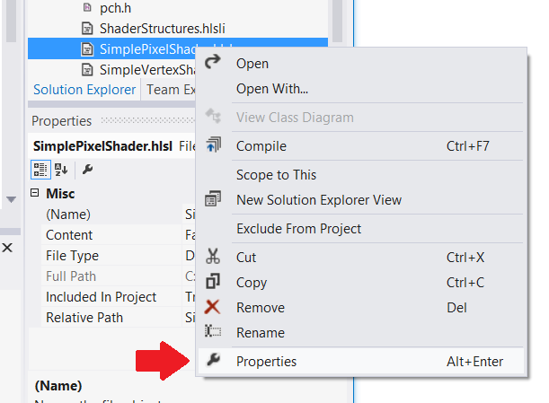
注意請務必為 HLSL 編譯器設定正確的目標功能層級:以滑鼠右鍵按一下 Visual Studio 中的 HLSL 來源檔案,選取 [屬性],然後變更 [HLSL 編譯器] -> [一般] 底下的 [著色器模型] 設定。 應用程式建立 Direct3D 著色器資源時,Direct3D 會根據硬體功能檢查此屬性。


這是建立輸入配置的著手之處,其對應至 Direct3D 9 中的頂點資料流宣告。 每個頂點資料結構須與頂點著色器使用的相同。在 Direct3D 11 中,我們對輸入配置有更多控制權;我們可以定義浮點向量的陣列大小和位元長度,以及指定頂點著色器的語意。 我們會建立 D3D11_INPUT_ELEMENT_DESC 結構,並用以通知 Direct3D 各頂點資料的外觀。 我們要等候載入頂點著色器並定義輸入配置,因為 API 會根據頂點著色器資源驗證輸入配置。 若輸入配置不相容,Direct3D 會擲回例外狀況。
各頂點資料必須儲存於系統記憶體中的相容類型。 DirectXMath 資料類型很實用,例如:DXGI_FORMAT_R32G32B32_FLOAT 對應至 XMFLOAT3。
注意常數緩衝區使用固定輸入配置,一次對應四個浮點數。 對於常數緩衝區資料,建議使用 XMFLOAT4 (及其衍生項目)。
在 Direct3D 11 中設定輸入配置
// Create input layout:
const D3D11_INPUT_ELEMENT_DESC vertexDesc[] =
{
    { "POSITION", 0, DXGI_FORMAT_R32G32B32_FLOAT,
        0, 0,  D3D11_INPUT_PER_VERTEX_DATA, 0 },

    { "COLOR",    0, DXGI_FORMAT_R32G32B32_FLOAT,
        0, 12, D3D11_INPUT_PER_VERTEX_DATA, 0 },
};
建立幾何資源
在 Direct3D 9 中,我們儲存幾何資源的方法是在 Direct3D 裝置建立緩衝區、鎖定記憶體,並將資料從 CPU 記憶體複製到 GPU 記憶體。
Direct3D 9
// Create vertex buffer:
VOID* pVertices;

// In Direct3D 9 we create the buffer, lock it, and copy the data from
// system memory to graphics memory.
m_pd3dDevice->CreateVertexBuffer(
    sizeof(CubeVertices),
    0,
    D3DFVF_XYZ | D3DFVF_DIFFUSE,
    D3DPOOL_MANAGED,
    &pVertexBuffer,
    NULL);

pVertexBuffer->Lock(
    0,
    sizeof(CubeVertices),
    &pVertices,
    0);

memcpy(pVertices, CubeVertices, sizeof(CubeVertices));
pVertexBuffer->Unlock();
DirectX 11 採用更簡單的程序。 API 會自動將資料從系統記憶體複製到 GPU。 使用 COM 智慧型指標有助於簡化程式設計流程。
DirectX 11
D3D11_SUBRESOURCE_DATA vertexBufferData = {0};
vertexBufferData.pSysMem = CubeVertices;
vertexBufferData.SysMemPitch = 0;
vertexBufferData.SysMemSlicePitch = 0;
CD3D11_BUFFER_DESC vertexBufferDesc(
    sizeof(CubeVertices),
    D3D11_BIND_VERTEX_BUFFER);

// This call allocates a device resource for the vertex buffer and copies
// in the data.
m_d3dDevice->CreateBuffer(
    &vertexBufferDesc,
    &vertexBufferData,
    &m_vertexBuffer
    );
實作轉譯鏈結
Direct3D 9 遊戲通常會使用以效果為基礎的轉譯鏈結。 這類轉譯鏈結會設定效果物件、提供物件需要的資源並轉譯每個階段。
Direct3D 9 轉譯鏈結
// Clear the render target and the z-buffer.
m_pd3dDevice->Clear(
    0, NULL,
    D3DCLEAR_TARGET | D3DCLEAR_ZBUFFER,
    D3DCOLOR_ARGB(0, 45, 50, 170),
    1.0f, 0
    );

// Set the effect technique
m_pEffect->SetTechnique("RenderSceneSimple");

// Rotate the cube 1 degree per frame.
D3DXMATRIX world;
D3DXMatrixRotationY(&world, D3DXToRadian(m_frameCount++));


// Set the matrices up using traditional functions.
m_pEffect->SetMatrix("g_mWorld", &world);
m_pEffect->SetMatrix("g_View", &m_view);
m_pEffect->SetMatrix("g_Projection", &m_projection);

// Render the scene using the Effects library.
if(SUCCEEDED(m_pd3dDevice->BeginScene()))
{
    // Begin rendering effect passes.
    UINT passes = 0;
    m_pEffect->Begin(&passes, 0);

    for (UINT i = 0; i < passes; i++)
    {
        m_pEffect->BeginPass(i);

        // Send vertex data to the pipeline.
        m_pd3dDevice->SetFVF(D3DFVF_XYZ | D3DFVF_DIFFUSE);
        m_pd3dDevice->SetStreamSource(
            0, pVertexBuffer,
            0, sizeof(VertexPositionColor)
            );
        m_pd3dDevice->SetIndices(pIndexBuffer);

        // Draw the cube.
        m_pd3dDevice->DrawIndexedPrimitive(
            D3DPT_TRIANGLELIST,
            0, 0, 8, 0, 12
            );
        m_pEffect->EndPass();
    }
    m_pEffect->End();

    // End drawing.
    m_pd3dDevice->EndScene();
}

// Present frame:
// Show the frame on the primary surface.
m_pd3dDevice->Present(NULL, NULL, NULL, NULL);
DirectX 11 轉譯鏈結仍會執行相同的工作,但轉譯階段的實作方式不同。 我們不會將細節放在 FX 檔案,導致轉譯技術對 C++ 程式碼來說或多或少不透明,因此我們會以 C++ 設定所有轉譯。
以下是轉譯鏈結的外觀。 我們需要提供載入頂點著色器後建立的輸入配置、提供每個著色器物件,以及為每個著色器指定要使用的常數緩衝區。 此範例不包含多個轉譯階段,但如果有,我們會針對每個階段執行類似的轉譯鏈結,請視需要變更設定。
Direct3D 11 轉譯鏈結
// Clear the back buffer.
const float midnightBlue[] = { 0.098f, 0.098f, 0.439f, 1.000f };
m_d3dContext->ClearRenderTargetView(
    m_renderTargetView.Get(),
    midnightBlue
    );

// Set the render target. This starts the drawing operation.
m_d3dContext->OMSetRenderTargets(
    1,  // number of render target views for this drawing operation.
    m_renderTargetView.GetAddressOf(),
    nullptr
    );


// Rotate the cube 1 degree per frame.
XMStoreFloat4x4(
    &m_constantBufferData.model,
    XMMatrixTranspose(XMMatrixRotationY(m_frameCount++ * XM_PI / 180.f))
    );

// Copy the updated constant buffer from system memory to video memory.
m_d3dContext->UpdateSubresource(
    m_constantBuffer.Get(),
    0,      // update the 0th subresource
    NULL,   // use the whole destination
    &m_constantBufferData,
    0,      // default pitch
    0       // default pitch
    );


// Send vertex data to the Input Assembler stage.
UINT stride = sizeof(VertexPositionColor);
UINT offset = 0;

m_d3dContext->IASetVertexBuffers(
    0,  // start with the first vertex buffer
    1,  // one vertex buffer
    m_vertexBuffer.GetAddressOf(),
    &stride,
    &offset
    );

m_d3dContext->IASetIndexBuffer(
    m_indexBuffer.Get(),
    DXGI_FORMAT_R16_UINT,
    0   // no offset
    );

m_d3dContext->IASetPrimitiveTopology(D3D11_PRIMITIVE_TOPOLOGY_TRIANGLELIST);
m_d3dContext->IASetInputLayout(m_inputLayout.Get());


// Set the vertex shader.
m_d3dContext->VSSetShader(
    m_vertexShader.Get(),
    nullptr,
    0
    );

// Set the vertex shader constant buffer data.
m_d3dContext->VSSetConstantBuffers(
    0,  // register 0
    1,  // one constant buffer
    m_constantBuffer.GetAddressOf()
    );


// Set the pixel shader.
m_d3dContext->PSSetShader(
    m_pixelShader.Get(),
    nullptr,
    0
    );


// Draw the cube.
m_d3dContext->DrawIndexed(
    m_indexCount,
    0,  // start with index 0
    0   // start with vertex 0
    );
交換鏈結是圖形基礎結構的一部分,因此我們使用 DXGI 交換鏈結呈現已完成的畫面格。 DXGI 會封鎖呼叫,直到下一個 vsync 才會傳回;接著遊戲迴圈可繼續執行下一個反覆項目。
使用 DirectX 11 將畫面格呈現至螢幕
m_swapChain->Present(1, 0);
系統會從 IFrameworkView::Run 方法實作的遊戲迴圈中呼叫我們剛剛建立的轉譯鏈結。 請見<第 3 部分:檢視區和遊戲迴圈>的說明。