HoloLens(第一代)和 Azure 310:物体检测
注意
混合现实学院教程在制作时考虑到了 HoloLens(第一代)和混合现实沉浸式头戴显示设备。 因此,对于仍在寻求这些设备的开发指导的开发人员而言,我们觉得很有必要保留这些教程。 我们不会在这些教程中更新 HoloLens 2 所用的最新工具集或集成相关的内容。 我们将维护这些教程,使之持续适用于支持的设备。 将来会发布一系列演示如何针对 HoloLens 2 进行开发的新教程。 此通知将在教程发布时通过指向这些教程的链接进行更新。
本课程介绍如何在混合现实应用程序中使用 Azure 自定义视觉“对象检测”功能来识别提供的图像中的自定义视觉内容及其空间位置。
此服务允许你使用对象图像训练机器学习模型。 然后,你将使用训练的模型来识别相似对象并大致了解其在现实世界中的位置,这由 Microsoft HoloLens 的摄像头捕获或连接到 PC 的用于沉浸式 (VR) 头戴显示设备的摄像头提供。
Azure 自定义视觉对象检测是一项 Microsoft 服务,可让开发人员生成自定义图像分类器。 然后,可以将这些分类器用于新图像,通过在图像本身中提供“框边界”来检测该新图像内的对象。 该服务提供了一个简单易用的在线门户来简化流程。 有关更多信息,请参阅以下链接:
完成本课程后,你会有一个混合现实应用程序,该应用程序将能够执行以下操作:
- 用户将可以凝视对象,此对象是他们使用 Azure 自定义视觉服务物体检测训练的对象。
- 用户将使用“点击”手势来捕获所查看内容的图像。
- 应用会将图像发送到 Azure 自定义视觉服务。
- 此时会显示服务的答复,该服务会将识别结果显示为世界空间文本。 这将通过利用 Microsoft HoloLens 的空间跟踪来实现,这是为了了解识别对象的世界位置,然后使用与在图像中检测到的内容关联的“标记”来提供标签文本。
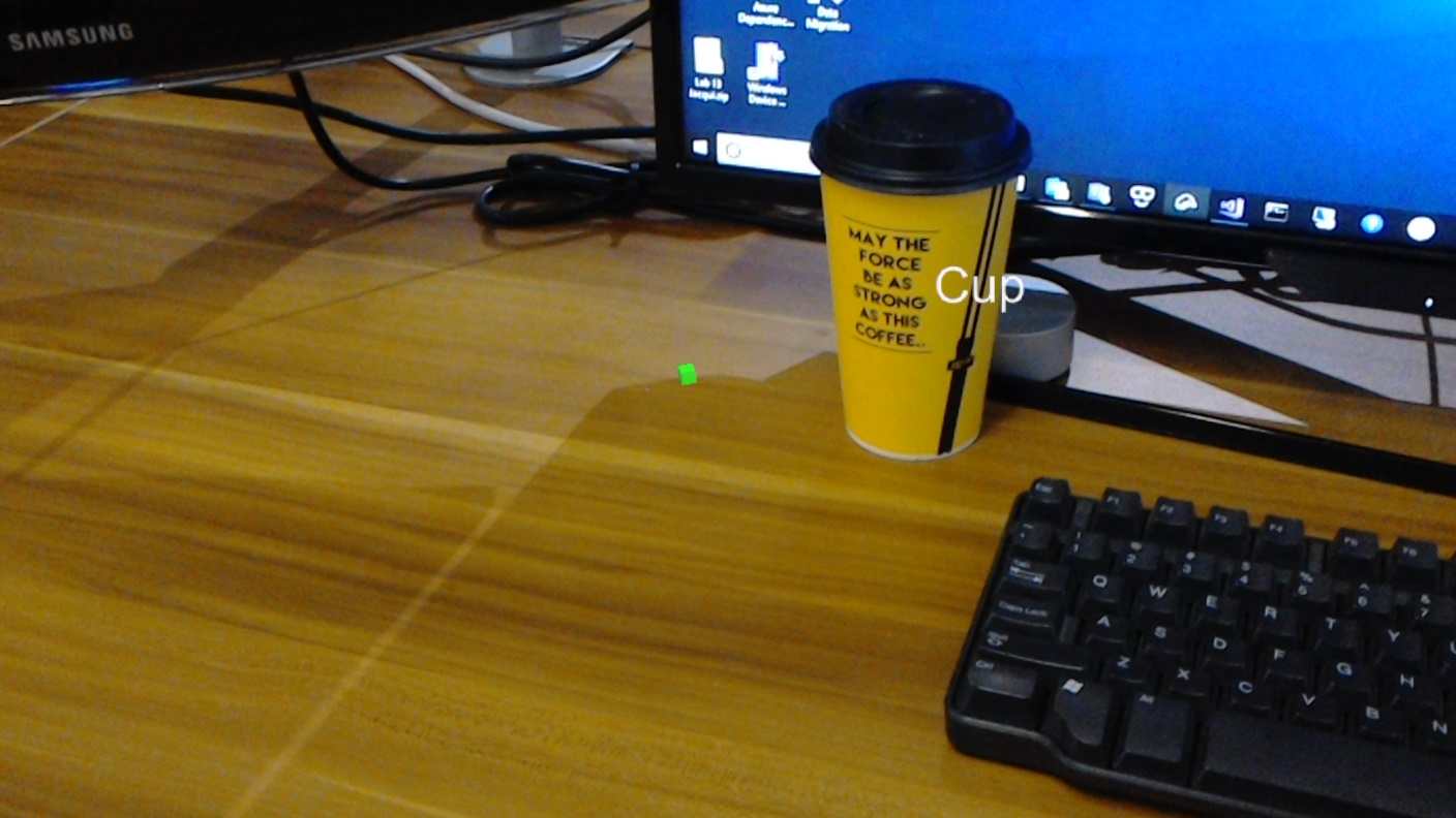
本课程还介绍了如何手动上传图像、创建标记,以及通过在提交的图像中设置“边界框”来训练服务识别不同的对象(在提供的示例中为杯子)。
重要
创建和使用应用后,开发人员应导航回 Azure 自定义视觉服务,识别该服务做出的预测,并确定其是否正确(通过标记服务遗漏的任何内容和调整“边界框”)。 然后,可以重新训练服务,这会增加识别现实世界对象的可能性。
本课程将介绍如何将 Azure 自定义视觉服务对象检测的结果引入基于 Unity 的示例应用程序。 你可以自行决定将这些概念应用到你可能会生成的自定义应用程序。
设备支持
| 课程 | HoloLens | 沉浸式头戴显示设备 |
|---|---|---|
| MR 和 Azure 310:对象检测 | ✔️ |
先决条件
注意
本教程专为具有 Unity 和 C# 基本经验的开发人员设计。 另请注意,本文档中的先决条件和书面说明在编写时(2018 年 7 月)已经过测试和验证。 可以随意使用最新的软件(如安装工具一文所列),但不应假设本课程中的信息将与你在较新的软件中找到的信息(而不是下面列出的内容)完全匹配。
建议在本课程中使用以下硬件和软件:
- 一台开发电脑
- 已启用开发人员模式的 Windows 10 Fall Creators Update(或更高版本)
- 最新的 Windows 10 SDK
- Unity 2017.4 LTS
- Visual Studio 2017
- 已启用开发人员模式的 Microsoft HoloLens
- 可访问 Internet 以便能够进行 Azure 设置和自定义视觉服务检索
- 对于希望自定义视觉识别的每个对象),需要一系列至少 15 幅的图像。 如果愿意,可以使用本课程已提供的图像,一系列杯子。
开始之前
- 为了避免在生成此项目时遇到问题,强烈建议在根文件夹或接近根的文件夹中创建本教程中提到的项目(长文件夹路径会在生成时导致问题)。
- 设置并测试 HoloLens。 如需对此的支持,请访问“HoloLens 安装程序”一文。
- 在开始开发新的 HoloLens 应用时,建议执行校准和传感器优化(有时 HoloLens 应用可以帮助为每个用户执行这些任务)。
有关校准的帮助信息,请单击此链接访问“HoloLens 校准”一文。
有关传感器优化的帮助信息,请单击此链接访问“HoloLens 传感器优化”一文。
第 1 章 - 自定义视觉门户
若要使用 Azure 自定义视觉服务,需要配置该服务的实例以供应用程序使用。
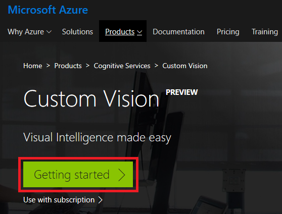
导航到自定义视觉服务主页。
单击入门。
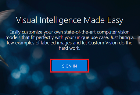
登录到自定义视觉门户。
如果你没有 Azure 帐户,需要创建一个。 如果你在课堂或实验室场景中跟着本教程学习,请让讲师或监督人员帮助设置你的新帐户。
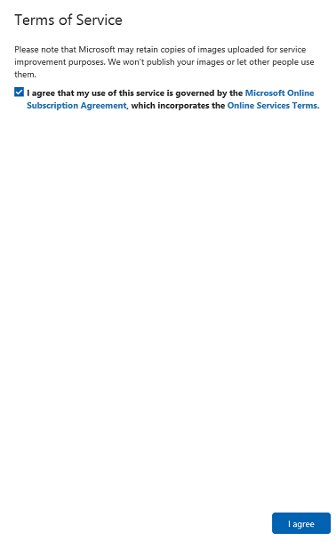
首次登录后,系统会显示“服务条款”面板。 单击复选框以“同意条款”。 然后单击我同意。
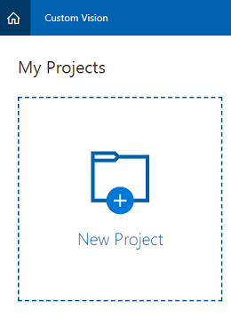
同意这些条款后,将来到我的项目部分。 单击“新建项目”。
右侧会出现一个选项卡,提示你为项目指定一些字段。
插入项目的名称
插入项目的描述(可选)
选择一个资源组或创建一个新资源组。 通过资源组,可监视和预配 Azure 资产集合、控制其访问权限并管理其计费。 建议保留与常用资源组下的单个项目(例如这些课程)关联的所有 Azure 服务。
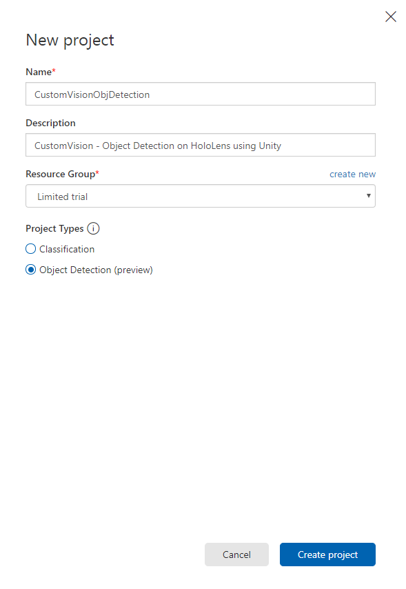
将“项目类型”设置为“对象检测(预览)”。
完成后,单击“创建项目”,然后你将被重定向到“自定义视觉服务”项目页面。
第 2 章 - 训练自定义视觉项目
进入自定义视觉门户后,你的主要目标是训练项目识别图像中的特定对象。
对于希望应用程序识别的每个对象,需要至少 15 幅图像。 你可以使用本课程提供的图像(一系列杯子)。
若要训练自定义视觉项目:
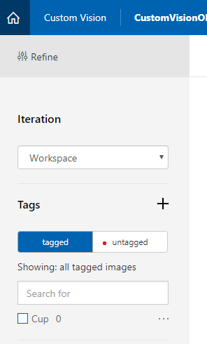
单击”标签”旁边的 + 按钮。
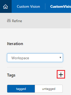
为将用于关联图像的标记添加名称。 在此示例中,我们将使用杯子的图像进行识别,因此已将标记命名为“杯子”。 完成后,单击“保存”。
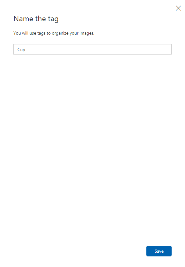
你会注意到你的“标记”已添加(可能需要重新加载页面才能显示)。
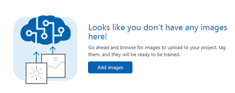
单击页面中央的“添加图像”。
单击浏览本地文件,然后浏览到要为某个对象上传的图像,最少为十五 (15) 幅。
提示
可以一次选择多幅图像进行上传。
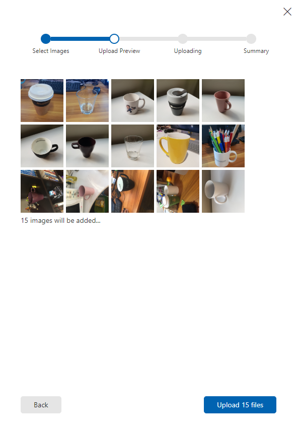
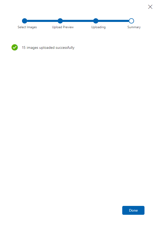
选择训练项目要使用的所有图像后,按上传文件。 文件将开始上传。 确认上传后,单击完成。
此时,图像已上传,但没有标记。
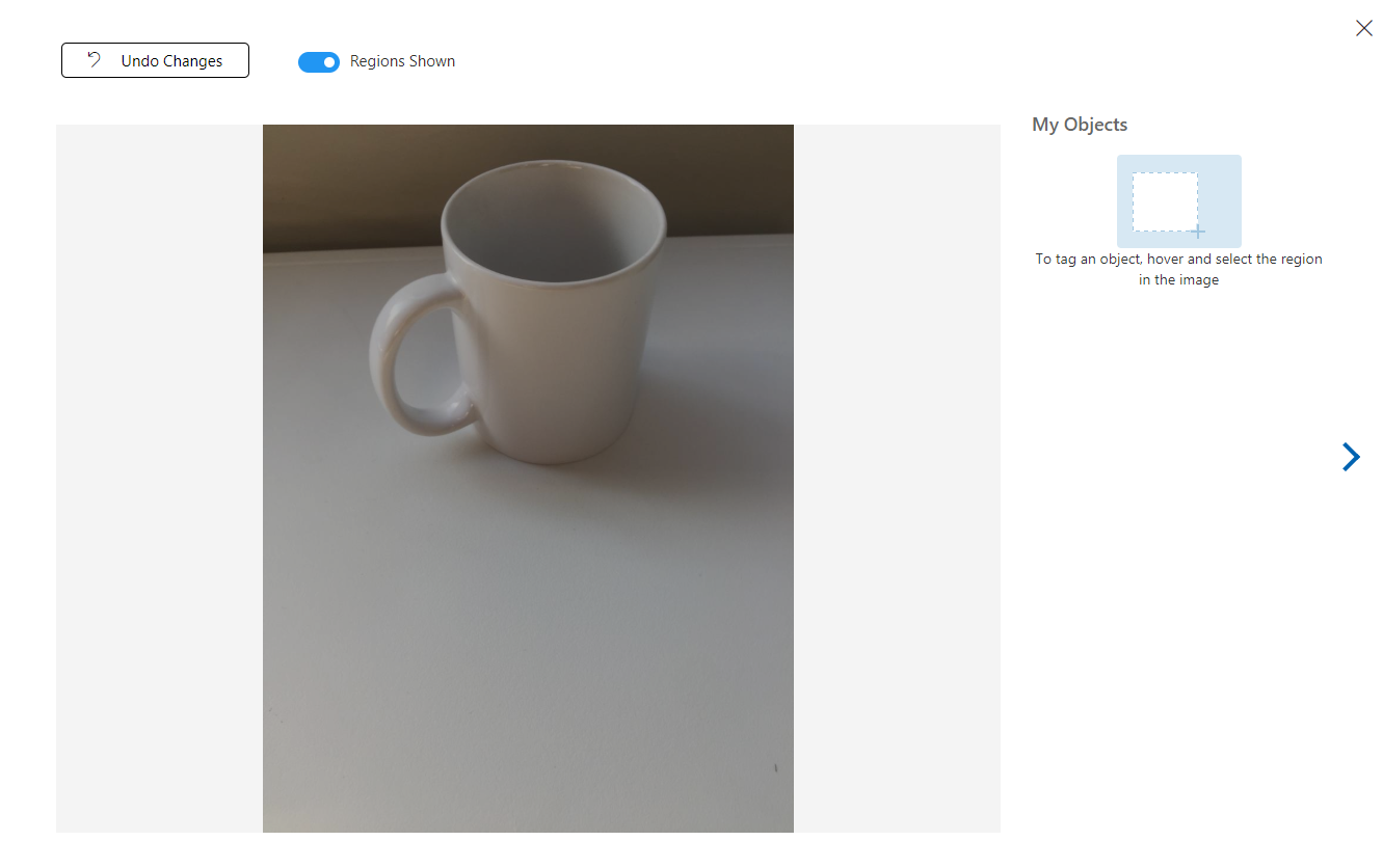
若要标记图像,请使用鼠标。 将鼠标悬停在图像上时,选择突出显示将帮助你在对象周围自动绘制选择。 如果不准确,可以绘制自己的选择。 这是通过按住鼠标左键单击并拖动选择区域以包含对象完成的。
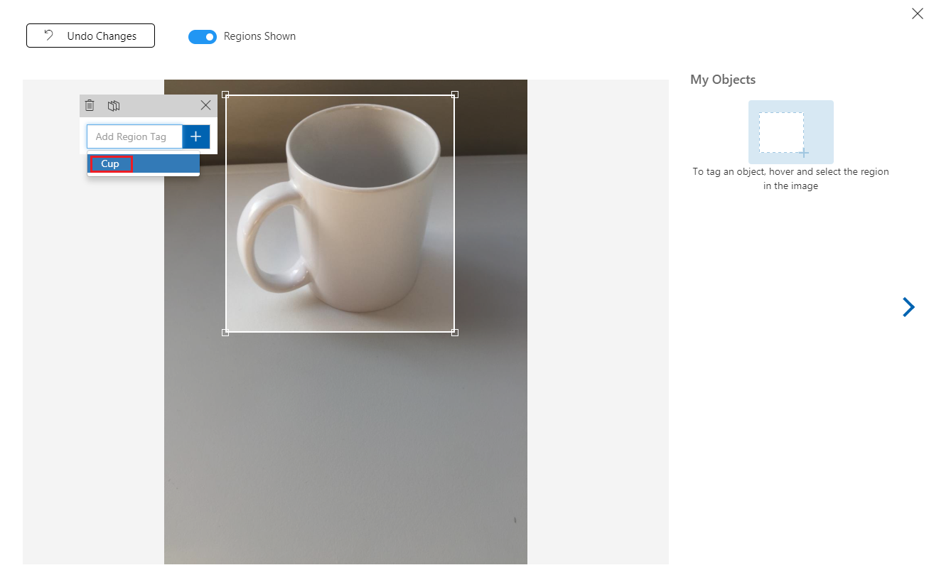
在图像中选择对象后,一个小提示会要求你添加“添加区域标记”。 选择前面创建的标记(在上述示例中为'Cup'),或者如果要添加更多标记,请输入然后单击“+ (加号)”按钮。
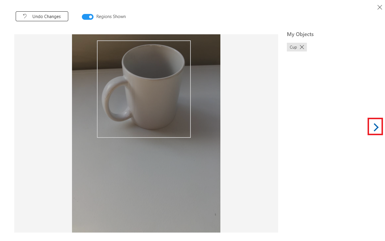
若要标记下一个图像,可以单击边栏选项卡右侧箭头,或单击边栏选项卡右上角的 X 关闭标记边栏选项卡,然后单击下一个图像。 准备好下一个图像后,重复相同的过程。 对已上传的所有图像执行此操作,直到将它们全部标记。
注意
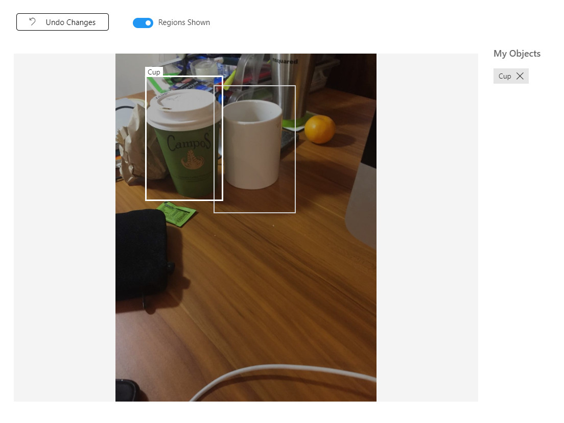
可以在同一图像中选择多个对象,如下图所示:
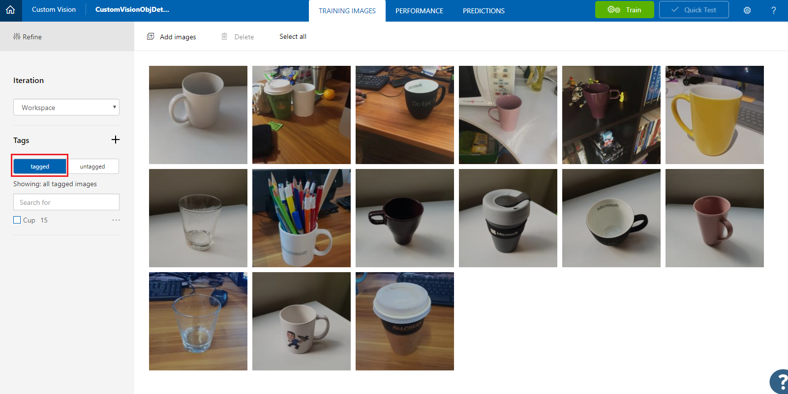
标记所有图像后,单击屏幕左侧的“已标记”按钮以显示标记的图像。
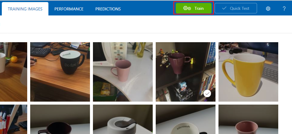
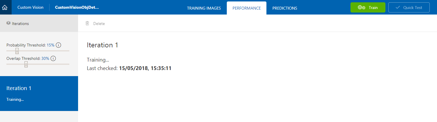
现在,你可以训练服务。 单击训练按钮,将开始第一个训练迭代。
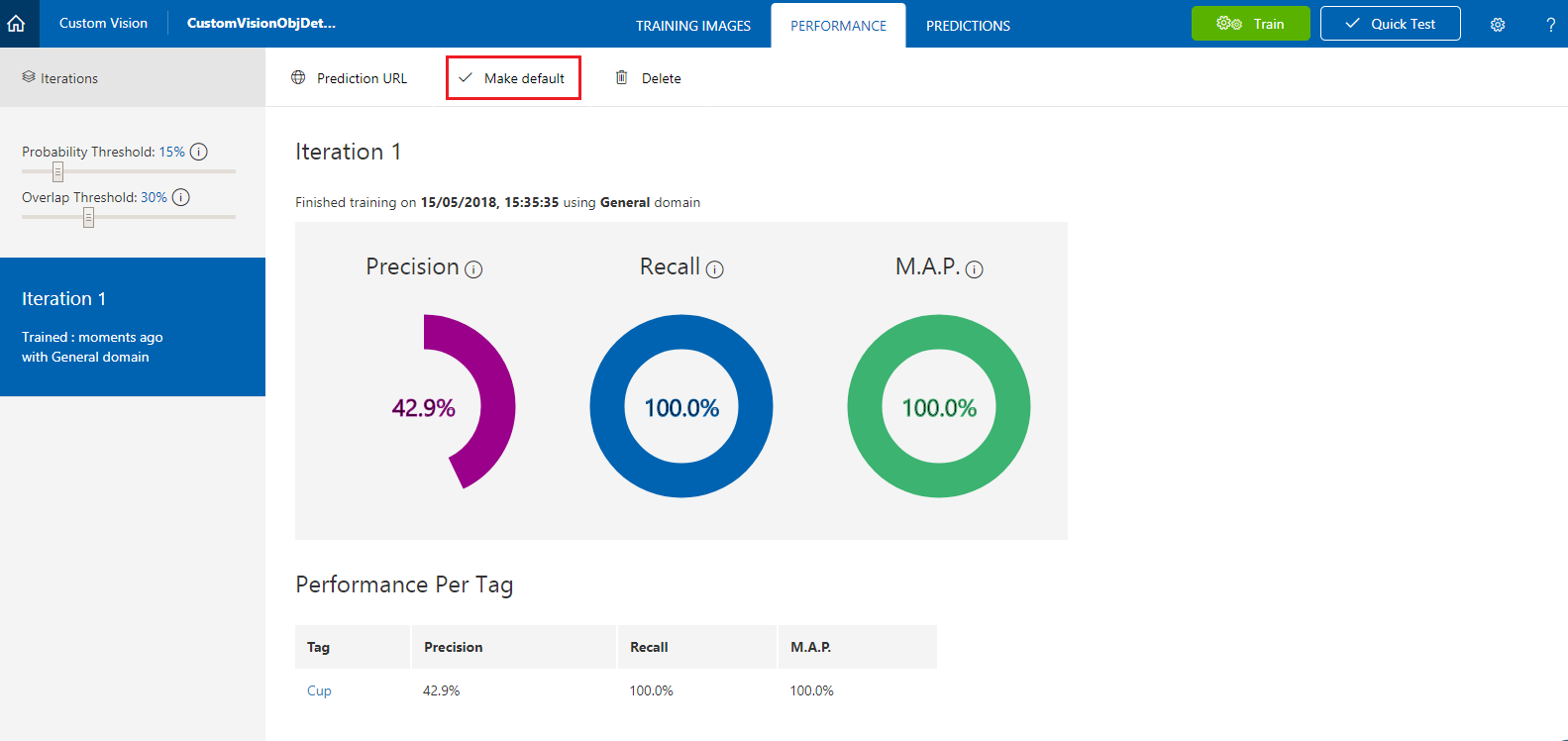
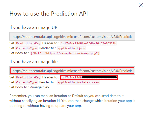
生成完成后,你将能够看到两个名为设为默认和预测 URL的按钮。 首先点击“设为默认”,然后单击“预测 URL”。
注意
据此提供的终结点设置为已标记为默认值的任何“迭代”。 因此,如果稍后进行新的迭代并将其更新为默认值,则无需更改代码。
单击预测 URL后,打开记事本,然后复制并粘贴 URL(又称为预测端点)和服务预测密钥,以便稍后在代码中需要时检索。
第 3 章 - 设置 Unity 项目
下面是用于使用混合现实进行开发的典型设置,因此,这对其他项目来说是一个不错的模板。
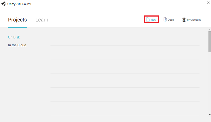
打开 Unity,单击“新建”。
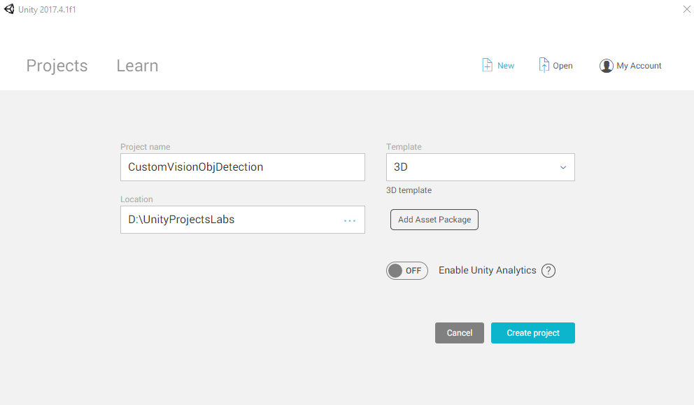
现在需要提供 Unity 项目名称。 插入 CustomVisionObjDetection。 确保将项目类型设置为“3D”,并且将“位置”设置为适合你的位置(请记住,越靠近根目录越好)。 然后,单击“创建项目”。
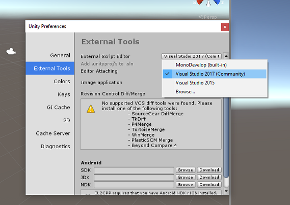
当 Unity 处于打开状态时,有必要检查默认“脚本编辑器”是否设置为“Visual Studio”。 转到“编辑”>“首选项”,然后在新窗口中导航到“外部工具”。 将“外部脚本编辑器”更改为“Visual Studio”。 关闭“首选项”窗口。
接下来,转到文件>生成设置,将平台切换到通用 Windows 平台,然后单击切换平台按钮。
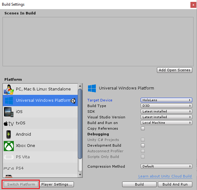
在同一“生成设置”窗口中,确保已设置以下内容:
将“目标设备”设置为“HoloLens”
将“生成类型”设置为“D3D”
将“SDK”设置为“最新安装的版本”
将“Visual Studio 版本”设置为“最新安装的版本”
将“生成并运行”设置为“本地计算机”
在“生成设置”中,其余设置目前应保留为默认值。
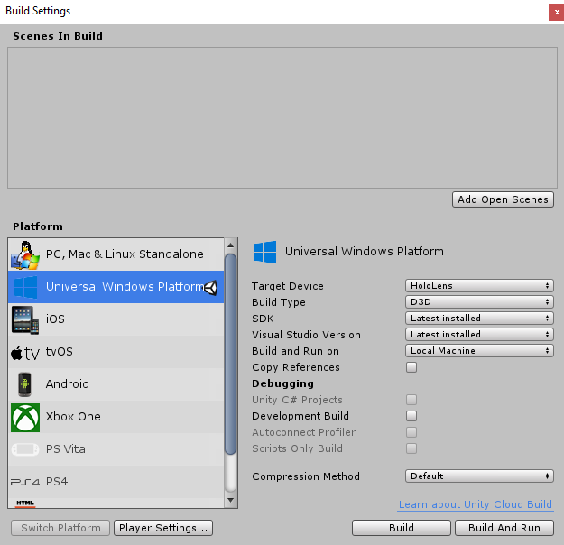
在同一“生成设置”窗口中,单击“播放器设置”按钮,这会在检查器所在的空间中打开相关面板。
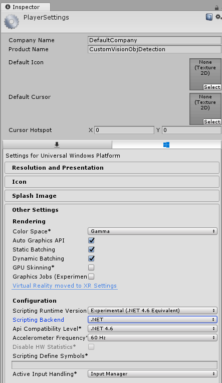
在此面板中,需要验证一些设置:
在“其他设置”选项卡中:
脚本运行时版本应为试验版(等效于 .Net 4.6),这将导致需要重启编辑器。
“脚本编写后端”应为“.NET”。
“API 兼容性级别”应为“.NET 4.6”。
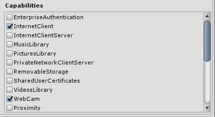
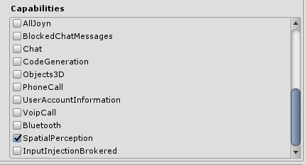
在“发布设置”选项卡的“功能”下,检查以下内容:
InternetClient
网络摄像头
SpatialPerception
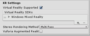
再往下滑面板,在XR 设置(在发布设置下方)中,勾选支持的虚拟现实,然后确保已添加 Windows Mixed Reality SDK。
返回生成设置,此时 Unity C# 项目不再灰显:勾选此内容旁边的复选框。
关闭“生成设置”窗口 。
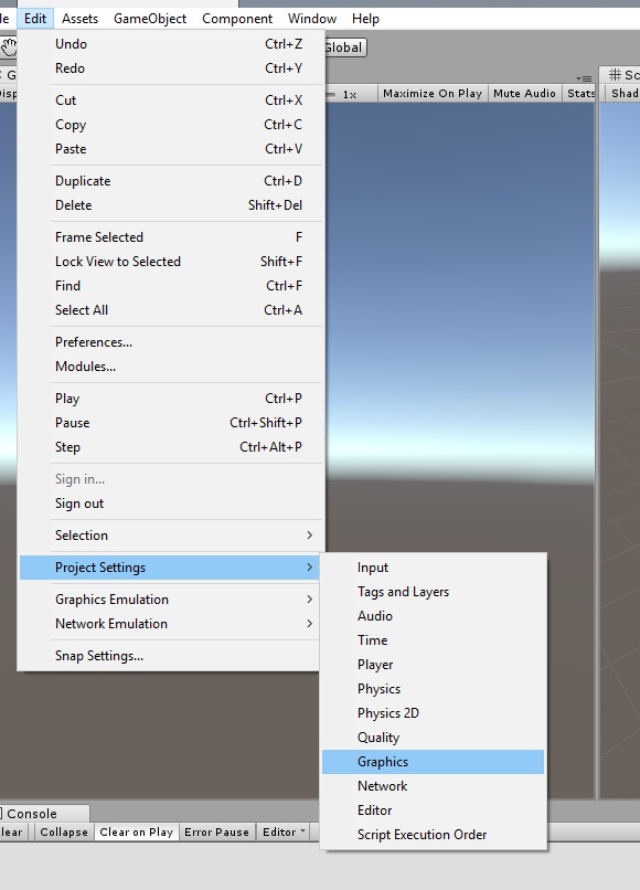
在编辑器中,单击编辑>项目设置>图形。
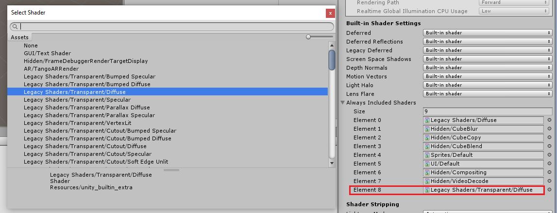
在检查器面板中,图形设置将打开。 向下滚动,直到看到名为“始终包含着色器”的数组。 通过增加“大小”变量来添加槽(此示例中,该变量为 8,因此我们将其增加为 9)。 将在数组的最后一个位置显示新槽,如下所示:
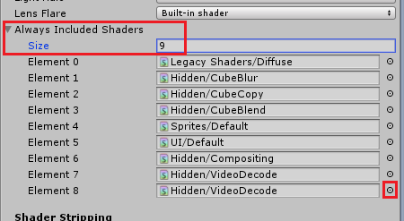
在槽中,单击槽旁边的小目标圆圈以打开着色器列表。 查找“旧版着色器/透明/漫射”着色器,然后双击它。
第 4 章 - 导入 CustomVisionObjDetection Unity 包
对于本课程,你将获得名为 Azure-MR-310.unitypackage 的 Unity 资产包。
[提示] Unity 支持的任何对象(包括整个场景)都可以打包到 .unitypackage 文件中,并导出/导入到其他项目中。 这是在不同 Unity 项目之间移动资产的最安全、最高效的方法。
可在此处找到需要下载的 Azure-MR-310 包。
在面前的 Unity 仪表板中,单击屏幕顶部菜单中的“资产”,然后单击“导入包”>“自定义包”。
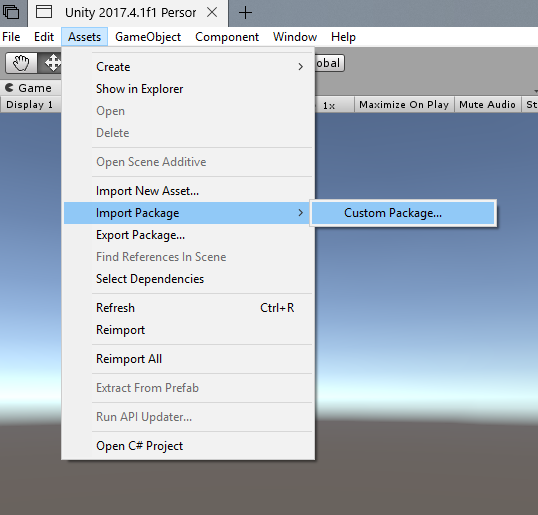
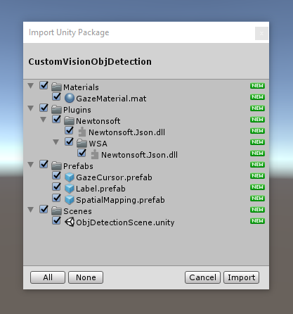
使用文件选择器选择 Azure-MR-310.unitypackage 包,然后单击“打开”。 此时会显示此资产的组件列表。 单击“导入”按钮以确认导入。
完成导入后,你会看到项目中文件夹已添加到“资产”文件夹中。 这是 Unity 项目的典型文件夹结构。
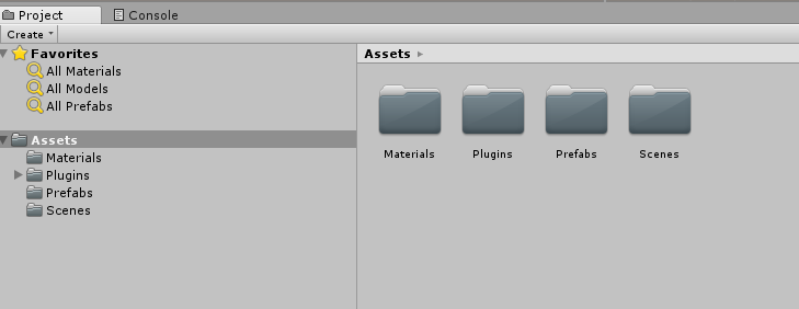
“材料”文件夹包含用于“凝视光标”的材料。
“插件”文件夹包含代码用于反序列化服务 web 响应的 Newtonsoft DLL。 若要允许 Unity 编辑器和 UWP 生成使用和生成库,文件夹和子文件夹中包含的两个不同版本是必需的。
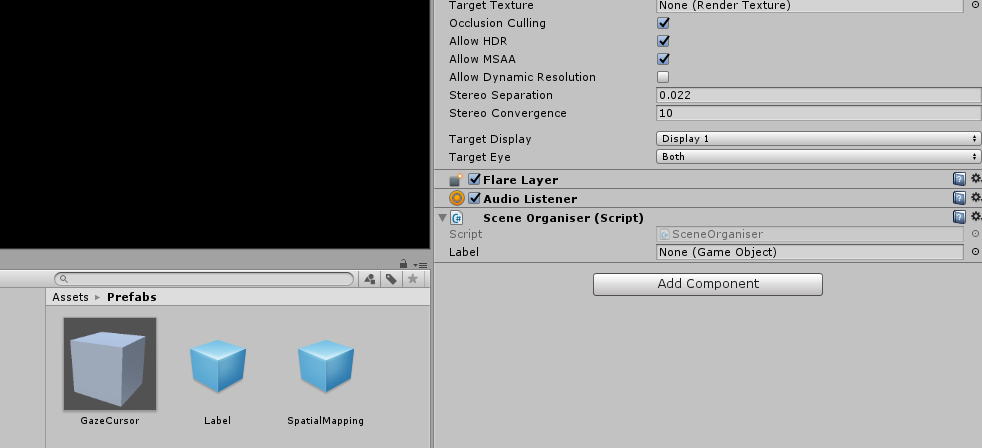
“预制件”文件夹包含场景中包含的预制件。 这些资源类型包括:
- GazeCursor,应用程序中使用的光标。 将与 SpatialMapping 预制件一起工作,以便能够放置在物理对象顶部的场景中。
- 标签,它用于在需要时显示场景中的对象标记的 UI 对象。
- SpatialMapping,它是一个对象,使应用程序能够使用 Microsoft HoloLens 空间跟踪来创建虚拟地图。
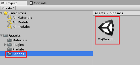
“场景”文件夹,它当前包含本课程的预生成场景。
打开项目面板中的场景文件夹,然后双击 ObjDetectionScene,加载用于本课程的场景。
注意
未包含任何代码,你将按照本课程编写代码。
第 5 章 - 创建 CustomVisionAnalyser 类。
此时,你已准备好编写一些代码。 需要从 CustomVisionAnalyser 类开始。
注意
下面显示的代码中对自定义视觉服务的调用是使用自定义视觉 REST API 进行的。 通过使用此 API,你将了解如何实现和使用这个 API(对于理解如何自己实现类似的东西很有用)。 请注意,Microsoft 提供了一个“自定义视觉 SDK”,这也可用于调用该服务。 有关更多信息,请访问自定义视觉 SDK 文章。
此类负责执行以下操作:
加载作为字节数组捕获的最新图像。
将字节数组发送到 Azure 自定义视觉服务实例进行分析。
以 JSON 字符串的形式接收响应。
反序列化响应并将生成的预测传递给 SceneOrganiser 类,该类将负责响应的显示方式。
若要创建此类,请执行以下操作:
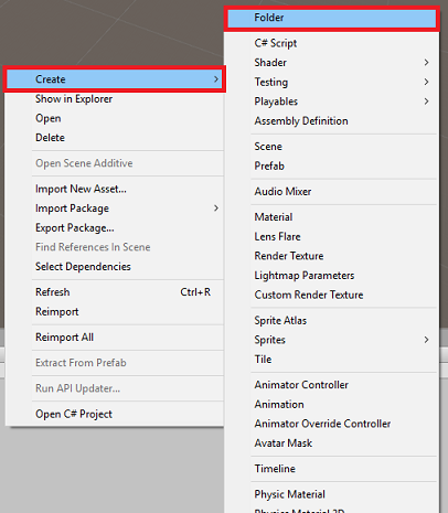
右键单击“项目”面板中的“资产文件夹”,然后单击“创建”>“文件夹”。 将该文件夹命名为“脚本”。
双击新创建的文件夹以打开它。
在文件夹中单击右键,然后单击“创建”>“C# 脚本”。 将脚本命名为“CustomVisionAnalyser”。
双击新的 CustomVisionAnalyser 脚本以使用 Visual Studio 将其打开。
请确保在文件顶部引用了以下命名空间:
using Newtonsoft.Json;
using System.Collections;
using System.IO;
using UnityEngine;
using UnityEngine.Networking;
在 CustomVisionAnalyser 类中,添加以下变量:
    /// <summary>
    /// Unique instance of this class
    /// </summary>
    public static CustomVisionAnalyser Instance;

    /// <summary>
    /// Insert your prediction key here
    /// </summary>
    private string predictionKey = "- Insert your key here -";

    /// <summary>
    /// Insert your prediction endpoint here
    /// </summary>
    private string predictionEndpoint = "Insert your prediction endpoint here";

    /// <summary>
    /// Bite array of the image to submit for analysis
    /// </summary>
    [HideInInspector] public byte[] imageBytes;
注意
请务必将“服务预测密钥”插入到 predictionKey 变量中,并将“预测终结点”插入到 predictionEndpoint 变量中。 你在前面的第 2 章第 14 步已将这些内容复制到了记事本。
现在需要添加 Awake() 的代码以初始化 Instance 变量:
    /// <summary>
    /// Initializes this class
    /// </summary>
    private void Awake()
    {
        // Allows this instance to behave like a singleton
        Instance = this;
    }
添加协同例程(与静态 GetImageAsByteArray() 方法一起),它将获取 ImageCapture 类捕获的图像的分析结果。
注意
在 AnalyseImageCapture 协同例程中,存在对 SceneOrganiser 类的调用,但你还尚未创建这个类。 因此,请暂时保留这些行的注释。
    /// <summary>
    /// Call the Computer Vision Service to submit the image.
    /// </summary>
    public IEnumerator AnalyseLastImageCaptured(string imagePath)
    {
        Debug.Log("Analyzing...");

        WWWForm webForm = new WWWForm();

        using (UnityWebRequest unityWebRequest = UnityWebRequest.Post(predictionEndpoint, webForm))
        {
            // Gets a byte array out of the saved image
            imageBytes = GetImageAsByteArray(imagePath);

            unityWebRequest.SetRequestHeader("Content-Type", "application/octet-stream");
            unityWebRequest.SetRequestHeader("Prediction-Key", predictionKey);

            // The upload handler will help uploading the byte array with the request
            unityWebRequest.uploadHandler = new UploadHandlerRaw(imageBytes);
            unityWebRequest.uploadHandler.contentType = "application/octet-stream";

            // The download handler will help receiving the analysis from Azure
            unityWebRequest.downloadHandler = new DownloadHandlerBuffer();

            // Send the request
            yield return unityWebRequest.SendWebRequest();

            string jsonResponse = unityWebRequest.downloadHandler.text;

            Debug.Log("response: " + jsonResponse);

            // Create a texture. Texture size does not matter, since
            // LoadImage will replace with the incoming image size.
            //Texture2D tex = new Texture2D(1, 1);
            //tex.LoadImage(imageBytes);
            //SceneOrganiser.Instance.quadRenderer.material.SetTexture("_MainTex", tex);

            // The response will be in JSON format, therefore it needs to be deserialized
            //AnalysisRootObject analysisRootObject = new AnalysisRootObject();
            //analysisRootObject = JsonConvert.DeserializeObject<AnalysisRootObject>(jsonResponse);

            //SceneOrganiser.Instance.FinaliseLabel(analysisRootObject);
        }
    }

    /// <summary>
    /// Returns the contents of the specified image file as a byte array.
    /// </summary>
    static byte[] GetImageAsByteArray(string imageFilePath)
    {
        FileStream fileStream = new FileStream(imageFilePath, FileMode.Open, FileAccess.Read);

        BinaryReader binaryReader = new BinaryReader(fileStream);

        return binaryReader.ReadBytes((int)fileStream.Length);
    }
删除 Start() 和 Update() 方法,因为不会用到它们。
返回到 Unity 之前,请务必在 Visual Studio 中保存所做的更改。
重要
不必担心代码可能看起来有错误,因为即将提供进一步的类,便会修复这些错误。
第 6 章 - 创建 CustomVisionObjects 类
现在将创建的类是 CustomVisionObjects 类。
此脚本包含许多对象,由其他类用于序列化和反序列化对自定义视觉服务的调用。
若要创建此类,请执行以下操作:
在“脚本”文件夹内右键单击,然后单击“创建”>“C# 脚本”。 调用脚本 CustomVisionObjects。
双击新的 CustomVisionObjects 脚本以使用 Visual Studio 将其打开。
请确保在文件顶部引用了以下命名空间:
using System;
using System.Collections.Generic;
using UnityEngine;
using UnityEngine.Networking;
删除 CustomVisionObjects 类中的 Start() 和 Update() 方法;此类现应为空。
警告
必须仔细遵循下一条说明。 如果将新的类声明放在 CustomVisionObjects 类中,将在第 10 章中收到编译错误,并指出找不到 AnalysisRootObject 和 BoundingBox。
在 CustomVisionObjects 类外部添加以下类。 Newtonsoft 库使用这些对象来序列化并反序列化响应数据:
// The objects contained in this script represent the deserialized version
// of the objects used by this application

/// <summary>
/// Web request object for image data
/// </summary>
class MultipartObject : IMultipartFormSection
{
    public string sectionName { get; set; }

    public byte[] sectionData { get; set; }

    public string fileName { get; set; }

    public string contentType { get; set; }
}

/// <summary>
/// JSON of all Tags existing within the project
/// contains the list of Tags
/// </summary>
public class Tags_RootObject
{
    public List<TagOfProject> Tags { get; set; }
    public int TotalTaggedImages { get; set; }
    public int TotalUntaggedImages { get; set; }
}

public class TagOfProject
{
    public string Id { get; set; }
    public string Name { get; set; }
    public string Description { get; set; }
    public int ImageCount { get; set; }
}

/// <summary>
/// JSON of Tag to associate to an image
/// Contains a list of hosting the tags,
/// since multiple tags can be associated with one image
/// </summary>
public class Tag_RootObject
{
    public List<Tag> Tags { get; set; }
}

public class Tag
{
    public string ImageId { get; set; }
    public string TagId { get; set; }
}

/// <summary>
/// JSON of images submitted
/// Contains objects that host detailed information about one or more images
/// </summary>
public class ImageRootObject
{
    public bool IsBatchSuccessful { get; set; }
    public List<SubmittedImage> Images { get; set; }
}

public class SubmittedImage
{
    public string SourceUrl { get; set; }
    public string Status { get; set; }
    public ImageObject Image { get; set; }
}

public class ImageObject
{
    public string Id { get; set; }
    public DateTime Created { get; set; }
    public int Width { get; set; }
    public int Height { get; set; }
    public string ImageUri { get; set; }
    public string ThumbnailUri { get; set; }
}

/// <summary>
/// JSON of Service Iteration
/// </summary>
public class Iteration
{
    public string Id { get; set; }
    public string Name { get; set; }
    public bool IsDefault { get; set; }
    public string Status { get; set; }
    public string Created { get; set; }
    public string LastModified { get; set; }
    public string TrainedAt { get; set; }
    public string ProjectId { get; set; }
    public bool Exportable { get; set; }
    public string DomainId { get; set; }
}

/// <summary>
/// Predictions received by the Service
/// after submitting an image for analysis
/// Includes Bounding Box
/// </summary>
public class AnalysisRootObject
{
    public string id { get; set; }
    public string project { get; set; }
    public string iteration { get; set; }
    public DateTime created { get; set; }
    public List<Prediction> predictions { get; set; }
}

public class BoundingBox
{
    public double left { get; set; }
    public double top { get; set; }
    public double width { get; set; }
    public double height { get; set; }
}

public class Prediction
{
    public double probability { get; set; }
    public string tagId { get; set; }
    public string tagName { get; set; }
    public BoundingBox boundingBox { get; set; }
}
返回到 Unity 之前,请务必在 Visual Studio 中保存所做的更改。
第 7 章 - 创建 SpatialMapping 类
此类将在场景中设置“空间映射碰撞体”,以便能够检测虚拟对象与真实对象之间的冲突。
若要创建此类,请执行以下操作:
在“脚本”文件夹内右键单击,然后单击“创建”>“C# 脚本”。 调用脚本 SpatialMapping。
双击新的 SpatialMapping 脚本以使用 Visual Studio 将其打开。
请确保在 SpatialMapping 类的上方引用了以下命名空间:
using UnityEngine;
using UnityEngine.XR.WSA;
然后在 SpatialMapping 类中的 Start() 方法上方添加以下变量:
    /// <summary>
    /// Allows this class to behave like a singleton
    /// </summary>
    public static SpatialMapping Instance;

    /// <summary>
    /// Used by the GazeCursor as a property with the Raycast call
    /// </summary>
    internal static int PhysicsRaycastMask;

    /// <summary>
    /// The layer to use for spatial mapping collisions
    /// </summary>
    internal int physicsLayer = 31;

    /// <summary>
    /// Creates environment colliders to work with physics
    /// </summary>
    private SpatialMappingCollider spatialMappingCollider;
添加 Awake() 和 Start():
    /// <summary>
    /// Initializes this class
    /// </summary>
    private void Awake()
    {
        // Allows this instance to behave like a singleton
        Instance = this;
    }

    /// <summary>
    /// Runs at initialization right after Awake method
    /// </summary>
    void Start()
    {
        // Initialize and configure the collider
        spatialMappingCollider = gameObject.GetComponent<SpatialMappingCollider>();
        spatialMappingCollider.surfaceParent = this.gameObject;
        spatialMappingCollider.freezeUpdates = false;
        spatialMappingCollider.layer = physicsLayer;

        // define the mask
        PhysicsRaycastMask = 1 << physicsLayer;

        // set the object as active one
        gameObject.SetActive(true);
    }
删除 Update() 方法。
返回到 Unity 之前,请务必在 Visual Studio 中保存所做的更改。
第 8 章 - 创建 GazeCursor 类
此类负责通过使用上一章中创建的 SpatialMappingCollider 在真实空间中的正确位置设置光标。
若要创建此类,请执行以下操作:
在“脚本”文件夹内右键单击,然后单击“创建”>“C# 脚本”。 调用脚本 GazeCursor
双击新的“GazeCursor”脚本以使用 Visual Studio 将其打开。
请确保在 GazeCursor 类的上方引用了以下命名空间:
using UnityEngine;然后在 GazeCursor 类中的 Start() 方法上方添加以下变量。
    /// <summary>
    /// The cursor (this object) mesh renderer
    /// </summary>
    private MeshRenderer meshRenderer;
使用以下代码更新 Start() 方法:
    /// <summary>
    /// Runs at initialization right after the Awake method
    /// </summary>
    void Start()
    {
        // Grab the mesh renderer that is on the same object as this script.
        meshRenderer = gameObject.GetComponent<MeshRenderer>();

        // Set the cursor reference
        SceneOrganiser.Instance.cursor = gameObject;
        gameObject.GetComponent<Renderer>().material.color = Color.green;

        // If you wish to change the size of the cursor you can do so here
        gameObject.transform.localScale = new Vector3(0.01f, 0.01f, 0.01f);
    }
使用以下代码更新 Update() 方法:
    /// <summary>
    /// Update is called once per frame
    /// </summary>
    void Update()
    {
        // Do a raycast into the world based on the user's head position and orientation.
        Vector3 headPosition = Camera.main.transform.position;
        Vector3 gazeDirection = Camera.main.transform.forward;

        RaycastHit gazeHitInfo;
        if (Physics.Raycast(headPosition, gazeDirection, out gazeHitInfo, 30.0f, SpatialMapping.PhysicsRaycastMask))
        {
            // If the raycast hit a hologram, display the cursor mesh.
            meshRenderer.enabled = true;
            // Move the cursor to the point where the raycast hit.
            transform.position = gazeHitInfo.point;
            // Rotate the cursor to hug the surface of the hologram.
            transform.rotation = Quaternion.FromToRotation(Vector3.up, gazeHitInfo.normal);
        }
        else
        {
            // If the raycast did not hit a hologram, hide the cursor mesh.
            meshRenderer.enabled = false;
        }
    }
注意
不必担心“找不到 SceneOrganiser 类”的错误,因为你将在下一章创建它。
返回到 Unity 之前,请务必在 Visual Studio 中保存所做的更改。
第 9 章 - 创建 SceneOrganiser 类
此类将:
通过将适当的组件附加到“主摄像头”来设置主摄像头。
检测到对象时,它将负责计算它在现实世界中的位置,并在其附近放置一个具有相应“标记名称”的“标记标签”。
若要创建此类,请执行以下操作:
在“脚本”文件夹内右键单击,然后单击“创建”>“C# 脚本”。 将脚本命名为“SceneOrganiser”。
双击新的 SceneOrganiser 脚本以使用 Visual Studio 将其打开。
请确保在 SceneOrganiser 类的上方引用了以下命名空间:
using System.Collections.Generic;
using System.Linq;
using UnityEngine;
然后在 SceneOrganiser 类中的 Start() 方法上方添加以下变量:
    /// <summary>
    /// Allows this class to behave like a singleton
    /// </summary>
    public static SceneOrganiser Instance;

    /// <summary>
    /// The cursor object attached to the Main Camera
    /// </summary>
    internal GameObject cursor;

    /// <summary>
    /// The label used to display the analysis on the objects in the real world
    /// </summary>
    public GameObject label;

    /// <summary>
    /// Reference to the last Label positioned
    /// </summary>
    internal Transform lastLabelPlaced;

    /// <summary>
    /// Reference to the last Label positioned
    /// </summary>
    internal TextMesh lastLabelPlacedText;

    /// <summary>
    /// Current threshold accepted for displaying the label
    /// Reduce this value to display the recognition more often
    /// </summary>
    internal float probabilityThreshold = 0.8f;

    /// <summary>
    /// The quad object hosting the imposed image captured
    /// </summary>
    private GameObject quad;

    /// <summary>
    /// Renderer of the quad object
    /// </summary>
    internal Renderer quadRenderer;
删除 Start() 和 Update() 方法。
在变量下方,添加 Awake() 方法,该方法将初始化类并设置场景。
    /// <summary>
    /// Called on initialization
    /// </summary>
    private void Awake()
    {
        // Use this class instance as singleton
        Instance = this;

        // Add the ImageCapture class to this Gameobject
        gameObject.AddComponent<ImageCapture>();

        // Add the CustomVisionAnalyser class to this Gameobject
        gameObject.AddComponent<CustomVisionAnalyser>();

        // Add the CustomVisionObjects class to this Gameobject
        gameObject.AddComponent<CustomVisionObjects>();
    }
添加 PlaceAnalysisLabel() 方法,该方法将实例化场景中的标签(此时用户看不到)。 它还会将四边形(也不可见)放置在图像所在的位置,并与现实世界重叠。 这一点很重要,因为分析后从服务中检索到的框坐标将追溯到此四边形中,以确定对象在现实世界中的大致位置。
    /// <summary>
    /// Instantiate a Label in the appropriate location relative to the Main Camera.
    /// </summary>
    public void PlaceAnalysisLabel()
    {
        lastLabelPlaced = Instantiate(label.transform, cursor.transform.position, transform.rotation);
        lastLabelPlacedText = lastLabelPlaced.GetComponent<TextMesh>();
        lastLabelPlacedText.text = "";
        lastLabelPlaced.transform.localScale = new Vector3(0.005f,0.005f,0.005f);

        // Create a GameObject to which the texture can be applied
        quad = GameObject.CreatePrimitive(PrimitiveType.Quad);
        quadRenderer = quad.GetComponent<Renderer>() as Renderer;
        Material m = new Material(Shader.Find("Legacy Shaders/Transparent/Diffuse"));
        quadRenderer.material = m;

        // Here you can set the transparency of the quad. Useful for debugging
        float transparency = 0f;
        quadRenderer.material.color = new Color(1, 1, 1, transparency);

        // Set the position and scale of the quad depending on user position
        quad.transform.parent = transform;
        quad.transform.rotation = transform.rotation;

        // The quad is positioned slightly forward in font of the user
        quad.transform.localPosition = new Vector3(0.0f, 0.0f, 3.0f);

        // The quad scale as been set with the following value following experimentation,
        // to allow the image on the quad to be as precisely imposed to the real world as possible
        quad.transform.localScale = new Vector3(3f, 1.65f, 1f);
        quad.transform.parent = null;
    }
添加 FinaliseLabel() 方法。 它负责:
- 使用具有最高置信度的预测标记设置标签文本。
- 调用四边形对象上“边界框”的计算(以前定的位),并将标签放置在场景中。
- 通过向“边界框”使用 Raycast 调整标签深度,该边界框应与现实世界中的对象发生冲突。
- 重置捕获进程以使用户捕获另一个图像。
    /// <summary>
    /// Set the Tags as Text of the last label created.
    /// </summary>
    public void FinaliseLabel(AnalysisRootObject analysisObject)
    {
        if (analysisObject.predictions != null)
        {
            lastLabelPlacedText = lastLabelPlaced.GetComponent<TextMesh>();
            // Sort the predictions to locate the highest one
            List<Prediction> sortedPredictions = new List<Prediction>();
            sortedPredictions = analysisObject.predictions.OrderBy(p => p.probability).ToList();
            Prediction bestPrediction = new Prediction();
            bestPrediction = sortedPredictions[sortedPredictions.Count - 1];

            if (bestPrediction.probability > probabilityThreshold)
            {
                quadRenderer = quad.GetComponent<Renderer>() as Renderer;
                Bounds quadBounds = quadRenderer.bounds;

                // Position the label as close as possible to the Bounding Box of the prediction
                // At this point it will not consider depth
                lastLabelPlaced.transform.parent = quad.transform;
                lastLabelPlaced.transform.localPosition = CalculateBoundingBoxPosition(quadBounds, bestPrediction.boundingBox);

                // Set the tag text
                lastLabelPlacedText.text = bestPrediction.tagName;

                // Cast a ray from the user's head to the currently placed label, it should hit the object detected by the Service.
                // At that point it will reposition the label where the ray HL sensor collides with the object,
                // (using the HL spatial tracking)
                Debug.Log("Repositioning Label");
                Vector3 headPosition = Camera.main.transform.position;
                RaycastHit objHitInfo;
                Vector3 objDirection = lastLabelPlaced.position;
                if (Physics.Raycast(headPosition, objDirection, out objHitInfo, 30.0f,   SpatialMapping.PhysicsRaycastMask))
                {
                    lastLabelPlaced.position = objHitInfo.point;
                }
            }
        }
        // Reset the color of the cursor
        cursor.GetComponent<Renderer>().material.color = Color.green;

        // Stop the analysis process
        ImageCapture.Instance.ResetImageCapture();
    }
添加 CalculateBoundingBoxPosition() 方法,该方法承载大量必要的计算,以转换从服务检索到的“边界框”坐标并将其按比例在四边形上重新创建。
    /// <summary>
    /// This method hosts a series of calculations to determine the position
    /// of the Bounding Box on the quad created in the real world
    /// by using the Bounding Box received back alongside the Best Prediction
    /// </summary>
    public Vector3 CalculateBoundingBoxPosition(Bounds b, BoundingBox boundingBox)
    {
        Debug.Log($"BB: left {boundingBox.left}, top {boundingBox.top}, width {boundingBox.width}, height {boundingBox.height}");

        double centerFromLeft = boundingBox.left + (boundingBox.width / 2);
        double centerFromTop = boundingBox.top + (boundingBox.height / 2);
        Debug.Log($"BB CenterFromLeft {centerFromLeft}, CenterFromTop {centerFromTop}");

        double quadWidth = b.size.normalized.x;
        double quadHeight = b.size.normalized.y;
        Debug.Log($"Quad Width {b.size.normalized.x}, Quad Height {b.size.normalized.y}");

        double normalisedPos_X = (quadWidth * centerFromLeft) - (quadWidth/2);
        double normalisedPos_Y = (quadHeight * centerFromTop) - (quadHeight/2);

        return new Vector3((float)normalisedPos_X, (float)normalisedPos_Y, 0);
    }
返回到 Unity 之前,请务必在 Visual Studio 中保存所做的更改。
重要
在继续之前,打开 CustomVisionAnalyser 类,并在 AnalyseLastImageCaptured() 方法中,取消注释以下行:
// Create a texture. Texture size does not matter, since
// LoadImage will replace with the incoming image size.
Texture2D tex = new Texture2D(1, 1);
tex.LoadImage(imageBytes);
SceneOrganiser.Instance.quadRenderer.material.SetTexture("_MainTex", tex);

// The response will be in JSON format, therefore it needs to be deserialized
AnalysisRootObject analysisRootObject = new AnalysisRootObject();
analysisRootObject = JsonConvert.DeserializeObject<AnalysisRootObject>(jsonResponse);

SceneOrganiser.Instance.FinaliseLabel(analysisRootObject);
注意
不必担心“找不到 ImageCapture 类”的消息,因为你将在下一章创建它。
第 10 章 – 创建 ImageCapture 类
要创建的下一个类是 ImageCapture 类。
此类负责执行以下操作:
- 使用 HoloLens 摄像头捕获图像并将其存储在“应用”文件夹中。
- 处理用户的点击手势。
若要创建此类,请执行以下操作:
转到之前创建的“脚本”文件夹。
在文件夹中单击右键,然后单击“创建”>“C# 脚本”。 将该脚本命名为“ImageCapture”。
双击新的“ImageCapture”脚本以使用 Visual Studio 将其打开。
在文件的顶部用以下代码替换命名空间:
using System;
using System.IO;
using System.Linq;
using UnityEngine;
using UnityEngine.XR.WSA.Input;
using UnityEngine.XR.WSA.WebCam;
然后在 ImageCapture 类中的 Start() 方法上方添加以下变量:
    /// <summary>
    /// Allows this class to behave like a singleton
    /// </summary>
    public static ImageCapture Instance;

    /// <summary>
    /// Keep counts of the taps for image renaming
    /// </summary>
    private int captureCount = 0;

    /// <summary>
    /// Photo Capture object
    /// </summary>
    private PhotoCapture photoCaptureObject = null;

    /// <summary>
    /// Allows gestures recognition in HoloLens
    /// </summary>
    private GestureRecognizer recognizer;

    /// <summary>
    /// Flagging if the capture loop is running
    /// </summary>
    internal bool captureIsActive;

    /// <summary>
    /// File path of current analysed photo
    /// </summary>
    internal string filePath = string.Empty;
现在需要添加 Awake() 和 Start() 方法的代码:
    /// <summary>
    /// Called on initialization
    /// </summary>
    private void Awake()
    {
        Instance = this;
    }

    /// <summary>
    /// Runs at initialization right after Awake method
    /// </summary>
    void Start()
    {
        // Clean up the LocalState folder of this application from all photos stored
        DirectoryInfo info = new DirectoryInfo(Application.persistentDataPath);
        var fileInfo = info.GetFiles();
        foreach (var file in fileInfo)
        {
            try
            {
                file.Delete();
            }
            catch (Exception)
            {
                Debug.LogFormat("Cannot delete file: ", file.Name);
            }
        }

        // Subscribing to the Microsoft HoloLens API gesture recognizer to track user gestures
        recognizer = new GestureRecognizer();
        recognizer.SetRecognizableGestures(GestureSettings.Tap);
        recognizer.Tapped += TapHandler;
        recognizer.StartCapturingGestures();
    }
实现一个在发生点击手势时要调用的处理程序:
    /// <summary>
    /// Respond to Tap Input.
    /// </summary>
    private void TapHandler(TappedEventArgs obj)
    {
        if (!captureIsActive)
        {
            captureIsActive = true;

            // Set the cursor color to red
            SceneOrganiser.Instance.cursor.GetComponent<Renderer>().material.color = Color.red;

            // Begin the capture loop
            Invoke("ExecuteImageCaptureAndAnalysis", 0);
        }
    }
重要
光标为“绿色”表示摄像头可以拍摄图像。 光标为“红色”表示摄像头处于繁忙状态。
添加应用程序用来启动图像捕获过程并存储图像的方法:
    /// <summary>
    /// Begin process of image capturing and send to Azure Custom Vision Service.
    /// </summary>
    private void ExecuteImageCaptureAndAnalysis()
    {
        // Create a label in world space using the ResultsLabel class
        // Invisible at this point but correctly positioned where the image was taken
        SceneOrganiser.Instance.PlaceAnalysisLabel();

        // Set the camera resolution to be the highest possible
        Resolution cameraResolution = PhotoCapture.SupportedResolutions.OrderByDescending
            ((res) => res.width * res.height).First();
        Texture2D targetTexture = new Texture2D(cameraResolution.width, cameraResolution.height);

        // Begin capture process, set the image format
        PhotoCapture.CreateAsync(true, delegate (PhotoCapture captureObject)
        {
            photoCaptureObject = captureObject;

            CameraParameters camParameters = new CameraParameters
            {
                hologramOpacity = 1.0f,
                cameraResolutionWidth = targetTexture.width,
                cameraResolutionHeight = targetTexture.height,
                pixelFormat = CapturePixelFormat.BGRA32
            };

            // Capture the image from the camera and save it in the App internal folder
            captureObject.StartPhotoModeAsync(camParameters, delegate (PhotoCapture.PhotoCaptureResult result)
            {
                string filename = string.Format(@"CapturedImage{0}.jpg", captureCount);
                filePath = Path.Combine(Application.persistentDataPath, filename);
                captureCount++;
                photoCaptureObject.TakePhotoAsync(filePath, PhotoCaptureFileOutputFormat.JPG, OnCapturedPhotoToDisk);
            });
        });
    }
添加将在捕获照片和准备分析照片时调用的处理程序。 然后,将结果传递给 CustomVisionAnalyser 进行分析。
    /// <summary>
    /// Register the full execution of the Photo Capture.
    /// </summary>
    void OnCapturedPhotoToDisk(PhotoCapture.PhotoCaptureResult result)
    {
        try
        {
            // Call StopPhotoMode once the image has successfully captured
            photoCaptureObject.StopPhotoModeAsync(OnStoppedPhotoMode);
        }
        catch (Exception e)
        {
            Debug.LogFormat("Exception capturing photo to disk: {0}", e.Message);
        }
    }

    /// <summary>
    /// The camera photo mode has stopped after the capture.
    /// Begin the image analysis process.
    /// </summary>
    void OnStoppedPhotoMode(PhotoCapture.PhotoCaptureResult result)
    {
        Debug.LogFormat("Stopped Photo Mode");

        // Dispose from the object in memory and request the image analysis
        photoCaptureObject.Dispose();
        photoCaptureObject = null;

        // Call the image analysis
        StartCoroutine(CustomVisionAnalyser.Instance.AnalyseLastImageCaptured(filePath));
    }

    /// <summary>
    /// Stops all capture pending actions
    /// </summary>
    internal void ResetImageCapture()
    {
        captureIsActive = false;

        // Set the cursor color to green
        SceneOrganiser.Instance.cursor.GetComponent<Renderer>().material.color = Color.green;

        // Stop the capture loop if active
        CancelInvoke();
    }
返回到 Unity 之前,请务必在 Visual Studio 中保存所做的更改。
第 11 章 - 在场景中设置脚本
现在,你已编写了此项目所需的所有代码,是时候在场景和预制件上设置脚本使它们正常运行了。
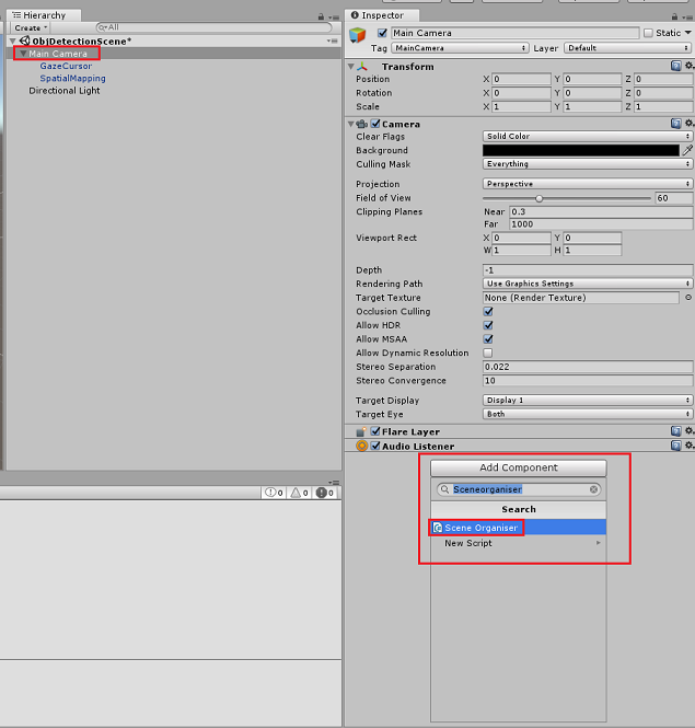
在“层次结构面板”中的“Unity 编辑器”中,选择“主摄像头”。
选择“主摄像头”后,在“检查器面板”中单击“添加组件”,搜索“SceneOrganiser”脚本,然后双击添加它。
在项目面板中,打开预制件文件夹,将标签预制件拖动到刚添加到主摄像头的 SceneOrganiser 脚本中的标签空引用目标输入区域,如下图所示:
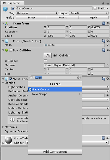
在“层次结构面板”中选择“主摄像头”的“GazeCursor”子级。
选择 GazeCursor 后,在检查器面板中单击添加组件,然后搜索 GazeCursor 脚本,双击添加它。
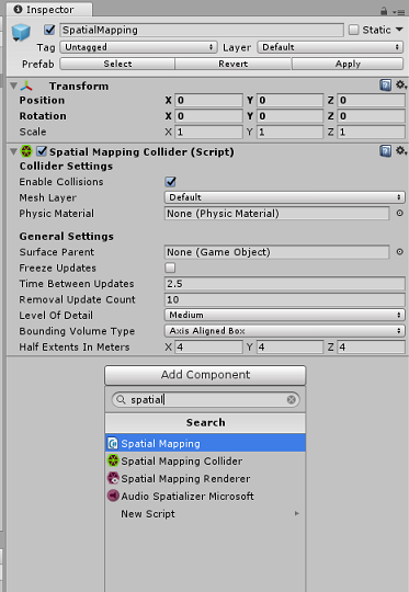
再在“层次结构面板”中选择“主摄像头”的“SpatialMapping”子级。
选择“SpatialMapping”后,在“检查器面板”中单击“添加组件”,然后搜索“SpatialMapping”脚本,并双击添加它。
在运行时,“SceneOrganiser”脚本中的代码将添加未设置的其余脚本。
第 12 章 - 生成前
若要对应用程序执行全面测试,需要将应用程序旁加载到 Microsoft HoloLens。
执行此操作之前,请确保:
第 3 章中提到的所有设置均正确设置。
将脚本“SceneOrganiser”附加到主摄像头对象。
将脚本“GazeCursor”附加到“GazeCursor”对象。
将脚本“SpatialMapping”附加到“SpatialMapping”对象。
在第 5 章中,第 6 步:
- 确保将“服务预测密钥”插入到 predictionKey变量中。
- 你已将你的“预测终结点”插入到 predictionEndpoint 变量中。
第 13 章 – 生成 UWP 解决方案并旁加载应用程序
现在,你可以将应用程序构建为一个 UWP 解决方案,你将能够将其部署到 Microsoft HoloLens。 若要开始生成过程,请执行以下操作:
转到“文件”>“生成设置”。
勾选“Unity C# 项目”。
单击“添加开放场景”。 这会将当前打开的场景添加到生成中。
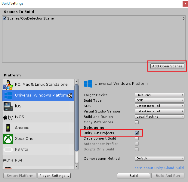
单击“生成”。 Unity 将启动“文件资源管理器”窗口,你需要在其中创建并选择一个文件夹来生成应用。 现在创建该文件夹,并将其命名为“应用”。 选择“应用”文件夹,然后,单击“选择文件夹”。
Unity 将开始将项目生成到“应用”文件夹。
Unity 完成生成(可能需要一些时间)后,会在生成位置打开“文件资源管理器”窗口(检查任务栏,因为它可能不会始终显示在窗口上方,但会通知你增加了一个新窗口)。
若要部署到 Microsoft HoloLens,你将需要该设备的 IP 地址(用于远程部署),并确保它还设置了“开发人员模式”。 要执行此操作:
佩戴 HoloLens 时,打开“设置”。
转到“网络和 Internet”>“Wi-Fi”>“高级选项”
记下 “IPv4” 地址。
接下来,导航回“设置”,然后转到“更新和安全”>“对于开发人员”
设置开发人员模式。
导航到新的 Unity 生成(“应用”文件夹)并使用 Visual Studio 打开解决方案文件。
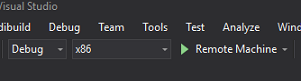
在“解决方案配置”中,选择“调试”。
在“解决方案平台”中,选择“x86,远程计算机”。 系统将提示你插入远程设备的 IP 地址(在本例中为 HoloLens,你之前记下了该地址)。
转到“生成”菜单,并单击“部署解决方案”,将应用程序旁加载到 HoloLens。
你的应用现在应显示在 Microsoft HoloLens 上的已安装应用列表中,随时可以启动!
要使用应用程序,请执行以下操作:
- 查看已使用“Azure 自定义视觉服务对象检测”训练的对象,并使用“点击手势”。
- 如果成功检测到该对象,则会出现带有标记名称的世界空间“标签文本”。
重要
每次捕获照片并将其发送到服务时,可以返回到“服务”页,并使用新捕获的图像重新训练服务。 一开始,可能还需要更正边界框来使其更准确并重新训练服务。
注意
如果 Microsoft HoloLens 传感器和/或 Unity 中的 SpatialTrackingComponent 未能相对于现实世界对象放置适当的碰撞体,则可能不会在对象附近显示放置的标签文本。 如果出现这种情况,请尝试在不同的表面上使用该应用程序。
自定义视觉对象检测应用程序
恭喜,你构建了一个利用 Azure 自定义视觉、对象检测 API 的混合现实应用,该 API 可识别图像中的对象,然后在 3D 空间中提供该对象的大致位置。
额外练习
练习 1
添加到“文本标签”中,使用半透明立方体将真实对象环绕在 3D 边界框中。
练习 2
训练自定义视觉服务来识别更多对象。
练习 3
在识别出对象时播放声音。
练习 4
使用 API 通过应用正在分析的相同图像来重新训练服务,从而使服务更准确(预测和训练同时进行)。