DrawingGroup.ClipGeometry Właściwość
Definicja
Ważne
Niektóre informacje odnoszą się do produktu w wersji wstępnej, który może zostać znacząco zmodyfikowany przed wydaniem. Firma Microsoft nie udziela żadnych gwarancji, jawnych lub domniemanych, w odniesieniu do informacji podanych w tym miejscu.
Pobiera lub ustawia region klipu w tym DrawingGroupobiekcie .
public:
 property System::Windows::Media::Geometry ^ ClipGeometry { System::Windows::Media::Geometry ^ get(); void set(System::Windows::Media::Geometry ^ value); };
public System.Windows.Media.Geometry ClipGeometry { get; set; }member this.ClipGeometry : System.Windows.Media.Geometry with get, setPublic Property ClipGeometry As GeometryWartość właściwości
Element Geometry używany do przycinania tego DrawingGroupobiektu . Wartość domyślna to null.
Przykłady
W tym przykładzie pokazano, jak zdefiniować region klipu dla obiektu Drawing.
Użyj obiektu , DrawingGroup aby zdefiniować klip dla obiektu Drawing. Klasa DrawingGroup jest jedynym typem Drawing obiektu, który umożliwia zdefiniowanie własnego regionu klipu.
Użyj elementu , Geometry aby opisać klip i zastosować go do ClipGeometry właściwości DrawingGroup obiektu.
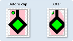
Ilustracja przedstawia DrawingGroup przed i po zastosowaniu wielokropkowego klipu.

W poniższym przykładzie użyto elementu ClipGeometry a DrawingGroup do zastosowania do kilku GeometryDrawing obiektów.
using System;
using System.Windows;
using System.Windows.Controls;
using System.Windows.Media;
using System.Windows.Media.Animation;
using System.Windows.Shapes;

namespace SDKSample
{
    /// <summary>
    /// Shows how to define a clip region for a DrawingGroup.
    /// </summary>
    public class ClipExample : Page
    {
        public ClipExample()
        {

            //
            // Create several GeometryDrawing objects.
            //

            // Create a rectangle.
            GeometryDrawing drawing1 = new GeometryDrawing(
                Brushes.Pink,
                null,
                new RectangleGeometry(new Rect(0,0,50,85))
                );

            //
            // Create a polygon.
            //
            PathFigure pLineFigure = new PathFigure();
            pLineFigure.StartPoint = new Point(25, 25);
            PolyLineSegment pLineSegment = new PolyLineSegment();
            pLineSegment.Points.Add(new Point(0, 50));
            pLineSegment.Points.Add(new Point(25, 75));
            pLineSegment.Points.Add(new Point(50, 50));
            pLineSegment.Points.Add(new Point(25, 25));
            pLineSegment.Points.Add(new Point(25, 0));
            pLineFigure.Segments.Add(pLineSegment);
            PathGeometry pGeometry = new PathGeometry();
            pGeometry.Figures.Add(pLineFigure);

            GeometryDrawing drawing2 = new GeometryDrawing(
                    Brushes.Lime,
                    new Pen(Brushes.Black, 10),
                    pGeometry
                );

            //
            // Create a circle.
            //
            GeometryDrawing drawing3 = new GeometryDrawing(
                    Brushes.Lime,
                    new Pen(Brushes.Black, 2),
                    new EllipseGeometry(new Point(10, 10), 5, 5)
                );

            // Create the DrawingGroup and add the
            // geometry drawings.
            DrawingGroup aDrawingGroup = new DrawingGroup();
            aDrawingGroup.Children.Add(drawing1);
            aDrawingGroup.Children.Add(drawing2);
            aDrawingGroup.Children.Add(drawing3);

            //
            // Create an EllipseGeometry and use it to
            // clip the DrawingGroup.
            //
            EllipseGeometry clipGeometry =
                new EllipseGeometry(new Point(25,50), 25, 50);
            aDrawingGroup.ClipGeometry = clipGeometry;

            // Use an Image control and a DrawingImage to
            // display the drawing.
            DrawingImage aDrawingImage = new DrawingImage(aDrawingGroup);

            // Freeze the DrawingImage for performance benefits.
            aDrawingImage.Freeze();

            Image anImage = new Image();
            anImage.Source = aDrawingImage;
            anImage.Stretch = Stretch.None;
            anImage.HorizontalAlignment = HorizontalAlignment.Left;

            // Create a border around the images and add it to the
            // page.
            Border imageBorder = new Border();
            imageBorder.BorderBrush = Brushes.Gray;
            imageBorder.BorderThickness = new Thickness(1);
            imageBorder.VerticalAlignment = VerticalAlignment.Top;
            imageBorder.HorizontalAlignment = HorizontalAlignment.Left;
            imageBorder.Margin = new Thickness(20);
            imageBorder.Child = anImage;

            this.Background = Brushes.White;
            this.Margin = new Thickness(20);
            this.Content = imageBorder;
        }
    }
}
<Page
  xmlns="http://schemas.microsoft.com/winfx/2006/xaml/presentation"
  xmlns:x="http://schemas.microsoft.com/winfx/2006/xaml"
  xmlns:PresentationOptions="http://schemas.microsoft.com/winfx/2006/xaml/presentation/options"
  xmlns:mc="http://schemas.openxmlformats.org/markup-compatibility/2006"
  mc:Ignorable="PresentationOptions"
  Background="White" Margin="20">

  <Border BorderBrush="Gray" BorderThickness="1"
    HorizontalAlignment="Left" VerticalAlignment="Top"
    Margin="20">
    <Image Stretch="None" HorizontalAlignment="Left">
      <Image.Source>
        <DrawingImage PresentationOptions:Freeze="True">
          <DrawingImage.Drawing>

            <!-- A DrawingGeometry with an elliptical clip region. -->
            <DrawingGroup>
              <GeometryDrawing Brush="Pink">
                <GeometryDrawing.Geometry>
                  <RectangleGeometry Rect="0,0,50,85" />
                </GeometryDrawing.Geometry>
              </GeometryDrawing>
              <GeometryDrawing Brush="Lime"
                Geometry="M 25,25 L 0,50 25,75 50,50 25,25 25,0">
                <GeometryDrawing.Pen>
                  <Pen Thickness="10" Brush="Black" />
                </GeometryDrawing.Pen>
              </GeometryDrawing>
              <GeometryDrawing Brush="Lime">
                <GeometryDrawing.Geometry>
                  <EllipseGeometry Center="10,10" RadiusX="5" RadiusY="5" />
                </GeometryDrawing.Geometry>
                <GeometryDrawing.Pen>
                  <Pen Thickness="2" Brush="Black" />
                </GeometryDrawing.Pen>
              </GeometryDrawing>

              <DrawingGroup.ClipGeometry>
                <EllipseGeometry Center="25,50" RadiusX="25" RadiusY="50" />
              </DrawingGroup.ClipGeometry>
            </DrawingGroup>
          </DrawingImage.Drawing>
        </DrawingImage>
      </Image.Source>
    </Image>
  </Border>


</Page>
Uwagi
Rysunki poza geometrią są przycięte z DrawingGroup momentu renderowania. Geometria nie musi być prostokątna; można na przykład użyć elementu EllipseGeometry do przycięcia do kształtu wielokropkowego.
DrawingGroup operacje są stosowane w następującej kolejności:
Informacje dotyczące właściwości zależności
| Pole identyfikatora | ClipGeometryProperty |
Właściwości metadanych ustawione na true |
Brak |