ジオメトリの概要
この概要では、Windows Presentation Foundation (WPF) の Geometry クラスを使用して図形を記述する方法を説明します。 このトピックでは、Geometry オブジェクトと Shape 要素の違いも示します。
ジオメトリとは
Geometry クラスとそれから派生するクラス (EllipseGeometry、PathGeometry、CombinedGeometry など) を使用すると、2D 図形のジオメトリを記述できます。 これらの幾何学的な記述には、画面を塗りつぶす図形を定義したり、ヒット テストやクリップ領域を定義するなど、多くの用途があります。 ジオメトリを使用して、アニメーション パスを定義することもできます。
Geometry オブジェクトは、四角形や円などの単純なものにすることも、2 つ以上のジオメトリ オブジェクトから作成された複合的なものにすることもできます。 円弧と曲線を記述できる PathGeometry および StreamGeometry クラスを使用すると、より複雑なジオメトリを作成できます。
Geometry は Freezable オブジェクトの一種であるため、Geometry オブジェクトはいくつかの特殊な機能を備えています。つまり、それらのオブジェクトをリソースとして宣言すること、複数のオブジェクト間で共有すること、読み取り専用にしてパフォーマンスを高めること、複製すること、スレッド セーフにすることができます。 Freezable オブジェクトで提供されるさまざまな機能について詳しくは、「Freezable オブジェクトの概要」をご覧ください。
ジオメトリと図形
Geometry と Shape クラスは、(たとえば、EllipseGeometry と Ellipse を比較した場合) 両方とも 2D 図形を記述するという点で似ているように見えますが、重要な違いがあります。
1 つには、Geometry クラスは Freezable クラスを継承し、Shape クラスは FrameworkElement を継承します。 これらは要素であるため、Shape オブジェクトは、それ自体をレンダリングしてレイアウト システムに加わることができますが、Geometry オブジェクトはできません。
Shape オブジェクトは Geometry オブジェクトよりも簡単に使用できますが、Geometry オブジェクトの方が汎用性があります。 Shape オブジェクトは 2D グラフィックスのレンダリングに使用されますが、Geometry オブジェクトは 2D グラフィックスの幾何学的領域の定義、クリッピング用の領域の定義、ヒット テスト用の領域の定義などに使用できます。
パス図形
1 つの Shape である Path クラスは、実際には Geometry を使用してそのコンテンツを記述します。 Geometry を使用して Path の Data プロパティを設定し、その Fill および Stroke プロパティを設定することで、Geometry をレンダリングできます。
ジオメトリを使用する一般的なプロパティ
これまでのセクションでは、図形の描画、アニメーション、クリッピングなどのさまざまな目的で、ジオメトリ オブジェクトを他のオブジェクトと共に使用できることを説明しました。 次の表に、Geometry オブジェクトを受け取るプロパティを持つクラスをいくつか示します。
| 種類 | プロパティ |
|---|---|
| DoubleAnimationUsingPath | PathGeometry |
| DrawingGroup | ClipGeometry |
| GeometryDrawing | Geometry |
| Path | Data |
| UIElement | Clip |
単純なジオメトリの種類
すべてのジオメトリの基底クラスは、抽象クラスの Geometry です。 Geometry クラスから派生するクラスは、単純なジオメトリ、パス ジオメトリ、複合ジオメトリという 3 つのカテゴリに大まかに分類できます。
単純なジオメトリのクラスには、LineGeometry、RectangleGeometry、EllipseGeometry が含まれ、線、四角形、円などの基本的な幾何学図形を作成するために使用されます。
LineGeometry は、線の始点と終点を指定して定義します。
RectangleGeometry は、その相対位置、高さおよび幅を指定する Rect 構造体で定義されます。 RadiusX と RadiusY プロパティを設定して、角丸四角形を作成できます。
EllipseGeometry は、中心点、x 半径、および y 半径によって定義されます。 レンダリングとクリッピング用の単純ジオメトリの作成方法を次の例に示します。
PathGeometry を使用するか、ジオメトリ オブジェクトを結合する方法でも、これらと同じ図形や、さらに複雑な図形を作成できますが、これらのクラスを使用すると、このような基本的な幾何学図形をより簡単に生成できます。
次の例は、LineGeometry を作成してレンダリングする方法を示しています。 前述のように、Geometry オブジェクトはそれ自体を描画できないため、この例では Path 図形を使用して線をレンダリングします。 線には領域がないため、Path の Fill プロパティを設定しても効果はありません。代わりに、Stroke および StrokeThickness プロパティのみが指定されています。 この例からの出力を次の図に示します。
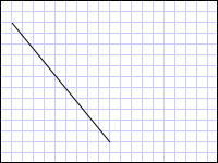
(10,20) から (100,130) まで描画された LineGeometry
<Path Stroke="Black" StrokeThickness="1" >
  <Path.Data>
    <LineGeometry StartPoint="10,20" EndPoint="100,130" />
  </Path.Data>
</Path>
LineGeometry myLineGeometry = new LineGeometry();
myLineGeometry.StartPoint = new Point(10,20);
myLineGeometry.EndPoint = new Point(100,130);

Path myPath = new Path();
myPath.Stroke = Brushes.Black;
myPath.StrokeThickness = 1;
myPath.Data = myLineGeometry;
Dim myLineGeometry As New LineGeometry()
myLineGeometry.StartPoint = New Point(10,20)
myLineGeometry.EndPoint = New Point(100,130)

Dim myPath As New Path()
myPath.Stroke = Brushes.Black
myPath.StrokeThickness = 1
myPath.Data = myLineGeometry
次の例は、EllipseGeometry を作成してレンダリングする方法を示しています。 この例では、EllipseGeometry の Center をポイント 50,50 に設定し、x 半径と y 半径の両方を 50 に設定します。これにより、直径 100 の円が作成されます。 楕円の内部は、Path 要素の Fill プロパティに値 (この例では Gold) を割り当てることで塗りつぶします。 この例からの出力を次の図に示します。
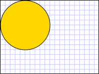
(50,50) に描画された EllipseGeometry
<Path Fill="Gold" Stroke="Black" StrokeThickness="1">
  <Path.Data>
    <EllipseGeometry Center="50,50" RadiusX="50" RadiusY="50" />
  </Path.Data>
</Path>
EllipseGeometry myEllipseGeometry = new EllipseGeometry();
myEllipseGeometry.Center = new Point(50, 50);
myEllipseGeometry.RadiusX = 50;
myEllipseGeometry.RadiusY = 50;

Path myPath = new Path();
myPath.Fill = Brushes.Gold;
myPath.Stroke = Brushes.Black;
myPath.StrokeThickness = 1;
myPath.Data = myEllipseGeometry;
Dim myEllipseGeometry As New EllipseGeometry()
myEllipseGeometry.Center = New Point(50, 50)
myEllipseGeometry.RadiusX = 50
myEllipseGeometry.RadiusY = 50

Dim myPath As New Path()
myPath.Fill = Brushes.Gold
myPath.Stroke = Brushes.Black
myPath.StrokeThickness = 1
myPath.Data = myEllipseGeometry
次の例は、RectangleGeometry を作成してレンダリングする方法を示しています。 四角形の位置と大きさは Rect 構造体によって定義されます。 位置は 50,50、高さと幅は両方とも 25 で、正方形が作成されます。 この例からの出力を次の図に示します。
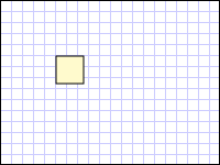
50,50 に描画された RectangleGeometry
<Path Fill="LemonChiffon" Stroke="Black" StrokeThickness="1">
  <Path.Data>
    <RectangleGeometry Rect="50,50,25,25" />
  </Path.Data>
</Path>
RectangleGeometry myRectangleGeometry = new RectangleGeometry();
myRectangleGeometry.Rect = new Rect(50,50,25,25);

Path myPath = new Path();
myPath.Fill = Brushes.LemonChiffon;
myPath.Stroke = Brushes.Black;
myPath.StrokeThickness = 1;
myPath.Data = myRectangleGeometry;
Dim myRectangleGeometry As New RectangleGeometry()
myRectangleGeometry.Rect = New Rect(50,50,25,25)

Dim myPath As New Path()
myPath.Fill = Brushes.LemonChiffon
myPath.Stroke = Brushes.Black
myPath.StrokeThickness = 1
myPath.Data = myRectangleGeometry
次の例は、EllipseGeometry をイメージのクリップ領域として使用する方法を示しています。 Image オブジェクトは、200 の Width と 150 の Height を指定して定義されています。 RadiusX 値が 100、RadiusY 値が 75、Center 値が 100,75 である EllipseGeometry が、イメージの Clip プロパティに設定されています。 イメージの楕円の領域内の部分だけが表示されます。 この例からの出力を次の図に示します。
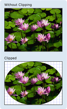
イメージ コントロールのクリップに使用される EllipseGeometry
<Image
  Source="sampleImages\Waterlilies.jpg"
  Width="200" Height="150" HorizontalAlignment="Left">
  <Image.Clip>
    <EllipseGeometry
      RadiusX="100"
      RadiusY="75"
      Center="100,75"/>
  </Image.Clip>
</Image>
// Create the image to clip.
Image myImage = new Image();
Uri imageUri =
    new Uri(@"C:\\Documents and Settings\\All Users\\Documents\My Pictures\\Sample Pictures\\Water lilies.jpg", UriKind.Relative);
myImage.Source = new BitmapImage(imageUri);
myImage.Width = 200;
myImage.Height = 150;
myImage.HorizontalAlignment = HorizontalAlignment.Left;

// Use an EllipseGeometry to define the clip region.
EllipseGeometry myEllipseGeometry = new EllipseGeometry();
myEllipseGeometry.Center = new Point(100, 75);
myEllipseGeometry.RadiusX = 100;
myEllipseGeometry.RadiusY = 75;
myImage.Clip = myEllipseGeometry;
' Create the image to clip.
Dim myImage As New Image()
Dim imageUri As New Uri("C:\\Documents and Settings\\All Users\\Documents\My Pictures\\Sample Pictures\\Water lilies.jpg", UriKind.Relative)
myImage.Source = New BitmapImage(imageUri)
myImage.Width = 200
myImage.Height = 150
myImage.HorizontalAlignment = HorizontalAlignment.Left

' Use an EllipseGeometry to define the clip region.
Dim myEllipseGeometry As New EllipseGeometry()
myEllipseGeometry.Center = New Point(100, 75)
myEllipseGeometry.RadiusX = 100
myEllipseGeometry.RadiusY = 75
myImage.Clip = myEllipseGeometry
パス ジオメトリ
PathGeometry クラスと、それと同等だが軽量である StreamGeometry クラスは、円弧、曲線、および線で構成される複数の複雑な図形を記述する手段を提供します。
PathGeometry の中核となるのは、PathFigure オブジェクトのコレクションです。各図形によって PathGeometry 内に個別の図形が記述されるので、このように呼ばれます。 各 PathFigure は、1 つ以上の PathSegment オブジェクトで構成され、このそれぞれで図形のセグメントが記述されます。
多くの種類のセグメントがあります。
| セグメントの種類 | 説明 | 例 |
|---|---|---|
| ArcSegment | 2 つの点を結ぶ楕円の円弧を作成します。 | 楕円の円弧を作成する。 |
| BezierSegment | 2 つの点を結ぶ 3 次ベジエ曲線を作成します。 | 3 次ベジエ曲線を作成する。 |
| LineSegment | 2 つの点を結ぶ直性を作成します。 | PathGeometry で LineSegment を作成する |
| PolyBezierSegment | 一続きの 3 次ベジエ曲線を作成します。 | PolyBezierSegment の種類のページを参照してください。 |
| PolyLineSegment | 一続きの直線を作成します。 | PolyLineSegment の種類のページを参照してください。 |
| PolyQuadraticBezierSegment | 一続きの 2 次ベジエ曲線を作成します。 | PolyQuadraticBezierSegment のページを参照してください。 |
| QuadraticBezierSegment | 2 次ベジエ曲線を作成します。 | 2 次ベジエ曲線を作成する。 |
PathFigure 内のセグメントは 1 つの幾何学図形に結合されて、各セグメントの終点が次のセグメントの始点になります。 PathFigure の StartPoint プロパティでは、最初のセグメントが描画される開始点を指定します。 後続の各セグメントは、前のセグメントの終点から始まります。 たとえば、10,50 から 10,150 までの縦線を定義するには、StartPoint プロパティを 10,50 に設定し、Point プロパティを 10,150 に設定して LineSegment を作成します。
次の例では、LineSegment を含む単一の PathFigure で構成される単純な PathGeometry を作成し、Path 要素を使用してそれを表示します。 PathFigure オブジェクトの StartPoint は 10,20 に設定され、LineSegment は終点の 100,130 を指定して定義されています。 次の図は、この例で作成した PathGeometry を示しています。

単一の LineSegment を含む PathGeometry
<Path Stroke="Black" StrokeThickness="1">
  <Path.Data>
    <PathGeometry>
      <PathGeometry.Figures>
        <PathFigure StartPoint="10,20">
          <PathFigure.Segments>
            <LineSegment Point="100,130"/>
          </PathFigure.Segments>
        </PathFigure>
      </PathGeometry.Figures>
    </PathGeometry>
  </Path.Data>
</Path>
// Create a figure that describes a
// line from (10,20) to (100,130).
PathFigure myPathFigure = new PathFigure();
myPathFigure.StartPoint = new Point(10,20);
myPathFigure.Segments.Add(
    new LineSegment(new Point(100,130),
    true /* IsStroked */ ));

/// Create a PathGeometry to contain the figure.
PathGeometry myPathGeometry = new PathGeometry();
myPathGeometry.Figures.Add(myPathFigure);

// Display the PathGeometry.
Path myPath = new Path();
myPath.Stroke = Brushes.Black;
myPath.StrokeThickness = 1;
myPath.Data = myPathGeometry;
' Create a figure that describes a
' line from (10,20) to (100,130).
Dim myPathFigure As New PathFigure()
myPathFigure.StartPoint = New Point(10,20)
myPathFigure.Segments.Add(New LineSegment(New Point(100,130), True)) ' IsStroked

''' Create a PathGeometry to contain the figure.
Dim myPathGeometry As New PathGeometry()
myPathGeometry.Figures.Add(myPathFigure)

' Display the PathGeometry.
Dim myPath As New Path()
myPath.Stroke = Brushes.Black
myPath.StrokeThickness = 1
myPath.Data = myPathGeometry
この例を前の LineGeometry 例と対比することは価値があります。 PathGeometry に使用される構文は、単純な LineGeometry に使用されるものよりもはるかに詳細であり、この場合は LineGeometry クラスを使用する方が理にかなっているかもしれませんが、PathGeometry の詳細な構文では非常に難解で複雑な幾何学的領域を実現できます。
より複雑なジオメトリは、 PathSegment オブジェクトの組み合わせを使用して作成できます。
次の例では、図形を作成するために、BezierSegment、LineSegment、および ArcSegment を使用します。 この例ではまず、始点 (前のセグメントの終点)、終点 (Point3)、2 つの制御点 (Point1 と Point2) の 4 つの点を定義して、3 次ベジエ曲線を作成します。 3 次ベジエ曲線の 2 つの制御点は磁石のように動作し、本来は直線になる部分を制御点の方へ引き寄せ、曲線を生成します。 最初の制御点である Point1 は曲線の開始部分に影響し、2 つ目の制御点である Point2 は曲線の終了部分に影響します。
次に、この例では LineSegment を追加します。これは、その前にある BezierSegment の終点から LineSegment プロパティで指定された点までの間で描画されます。
そして、例では ArcSegment を追加します。これは、その前の LineSegment の終点から Point プロパティで指定された点まで描画されます。 さらに、例では円弧の x および y 半径 (Size)、回転角度 (RotationAngle)、結果の円弧の角度の大きさを示すフラグ (IsLargeArc)、および円弧が描画される方向を示す値 (SweepDirection) も指定します。 この例で作成した図形を次の図に示します。
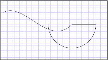
PathGeometry
<Path Stroke="Black" StrokeThickness="1" >
  <Path.Data>
    <PathGeometry>
      <PathGeometry.Figures>
        <PathFigure StartPoint="10,50">
          <PathFigure.Segments>
            <BezierSegment
              Point1="100,0"
              Point2="200,200"
              Point3="300,100"/>
            <LineSegment Point="400,100" />
            <ArcSegment
              Size="50,50" RotationAngle="45"
              IsLargeArc="True" SweepDirection="Clockwise"
              Point="200,100"/>
          </PathFigure.Segments>
        </PathFigure>
      </PathGeometry.Figures>
    </PathGeometry>
  </Path.Data>
</Path>
// Create a figure.
PathFigure myPathFigure = new PathFigure();
myPathFigure.StartPoint = new Point(10,50);
myPathFigure.Segments.Add(
    new BezierSegment(
        new Point(100,0),
        new Point(200,200),
        new Point(300,100),
        true /* IsStroked */  ));
myPathFigure.Segments.Add(
    new LineSegment(
        new Point(400,100),
        true /* IsStroked */ ));
myPathFigure.Segments.Add(
    new ArcSegment(
        new Point(200,100),
        new Size(50,50),
        45,
        true, /* IsLargeArc */
        SweepDirection.Clockwise,
        true /* IsStroked */ ));

/// Create a PathGeometry to contain the figure.
PathGeometry myPathGeometry = new PathGeometry();
myPathGeometry.Figures.Add(myPathFigure);

// Display the PathGeometry.
Path myPath = new Path();
myPath.Stroke = Brushes.Black;
myPath.StrokeThickness = 1;
myPath.Data = myPathGeometry;
' Create a figure.
Dim myPathFigure As New PathFigure()
myPathFigure.StartPoint = New Point(10,50)
myPathFigure.Segments.Add(New BezierSegment(New Point(100,0), New Point(200,200), New Point(300,100), True)) ' IsStroked
myPathFigure.Segments.Add(New LineSegment(New Point(400,100), True)) ' IsStroked
myPathFigure.Segments.Add(New ArcSegment(New Point(200,100), New Size(50,50), 45, True, SweepDirection.Clockwise, True)) ' IsStroked  -  IsLargeArc

''' Create a PathGeometry to contain the figure.
Dim myPathGeometry As New PathGeometry()
myPathGeometry.Figures.Add(myPathFigure)

' Display the PathGeometry.
Dim myPath As New Path()
myPath.Stroke = Brushes.Black
myPath.StrokeThickness = 1
myPath.Data = myPathGeometry
さらに複雑なジオメトリは、PathGeometry 内で複数の PathFigure オブジェクトを使用して作成できます。
次の例では、2 つの PathFigure オブジェクトを持つ PathGeometry を作成し、それぞれに複数の PathSegment オブジェクトが含まれます。 上の例の PathFigure と、PolyLineSegment と QuadraticBezierSegment を含む PathFigure が使用されます。 PolyLineSegment は点の配列を指定して定義され、QuadraticBezierSegment は制御点と終点を指定して定義されます。 この例で作成した図形を次の図に示します。
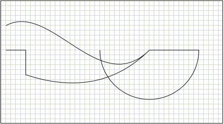
複数の図形を使用する PathGeometry
<Path Stroke="Black" StrokeThickness="1" >
  <Path.Data>
    <PathGeometry>
      <PathGeometry.Figures>
        <PathFigure StartPoint="10,50">
          <PathFigure.Segments>
            <BezierSegment
              Point1="100,0"
              Point2="200,200"
              Point3="300,100"/>
            <LineSegment Point="400,100" />
            <ArcSegment
              Size="50,50" RotationAngle="45"
              IsLargeArc="True" SweepDirection="Clockwise"
              Point="200,100"/>
          </PathFigure.Segments>
        </PathFigure>

        <PathFigure StartPoint="10,100">
          <PathFigure.Segments>
            <PolyLineSegment Points="50,100 50,150" />
            <QuadraticBezierSegment Point1="200,200" Point2="300,100"/>
          </PathFigure.Segments>
        </PathFigure>
      </PathGeometry.Figures>
    </PathGeometry>
  </Path.Data>
</Path>
PathGeometry myPathGeometry = new PathGeometry();

// Create a figure.
PathFigure pathFigure1 = new PathFigure();
pathFigure1.StartPoint = new Point(10,50);
pathFigure1.Segments.Add(
    new BezierSegment(
        new Point(100,0),
        new Point(200,200),
        new Point(300,100),
        true /* IsStroked */ ));
pathFigure1.Segments.Add(
    new LineSegment(
        new Point(400,100),
        true /* IsStroked */ ));
pathFigure1.Segments.Add(
    new ArcSegment(
        new Point(200,100),
        new Size(50,50),
        45,
        true, /* IsLargeArc */
        SweepDirection.Clockwise,
        true /* IsStroked */ ));
myPathGeometry.Figures.Add(pathFigure1);

// Create another figure.
PathFigure pathFigure2 = new PathFigure();
pathFigure2.StartPoint = new Point(10,100);
Point[] polyLinePointArray =
    new Point[]{ new Point(50, 100), new Point(50, 150)};
PolyLineSegment myPolyLineSegment = new PolyLineSegment();
myPolyLineSegment.Points =
    new PointCollection(polyLinePointArray);
pathFigure2.Segments.Add(myPolyLineSegment);
pathFigure2.Segments.Add(
    new QuadraticBezierSegment(
        new Point(200,200),
        new Point(300,100),
        true /* IsStroked */ ));
myPathGeometry.Figures.Add(pathFigure2);

// Display the PathGeometry.
Path myPath = new Path();
myPath.Stroke = Brushes.Black;
myPath.StrokeThickness = 1;
myPath.Data = myPathGeometry;
Dim myPathGeometry As New PathGeometry()

' Create a figure.
Dim pathFigure1 As New PathFigure()
pathFigure1.StartPoint = New Point(10,50)
pathFigure1.Segments.Add(New BezierSegment(New Point(100,0), New Point(200,200), New Point(300,100), True)) ' IsStroked
pathFigure1.Segments.Add(New LineSegment(New Point(400,100), True)) ' IsStroked
pathFigure1.Segments.Add(New ArcSegment(New Point(200,100), New Size(50,50), 45, True, SweepDirection.Clockwise, True)) ' IsStroked  -  IsLargeArc
myPathGeometry.Figures.Add(pathFigure1)

' Create another figure.
Dim pathFigure2 As New PathFigure()
pathFigure2.StartPoint = New Point(10,100)
Dim polyLinePointArray() As Point = { New Point(50, 100), New Point(50, 150)}
Dim myPolyLineSegment As New PolyLineSegment()
myPolyLineSegment.Points = New PointCollection(polyLinePointArray)
pathFigure2.Segments.Add(myPolyLineSegment)
pathFigure2.Segments.Add(New QuadraticBezierSegment(New Point(200,200), New Point(300,100), True)) ' IsStroked
myPathGeometry.Figures.Add(pathFigure2)

' Display the PathGeometry.
Dim myPath As New Path()
myPath.Stroke = Brushes.Black
myPath.StrokeThickness = 1
myPath.Data = myPathGeometry
StreamGeometry
StreamGeometry は、PathGeometry クラスと同様に、曲線、円弧、直線を含めることができる複雑な幾何学図形を定義します。 PathGeometry とは異なり、StreamGeometry のコンテンツは、データ バインディング、アニメーション、変更をサポートしていません。 複雑なジオメトリを記述する必要があるが、データ バインディング、アニメーション、または変更をサポートするオーバーヘッドが望ましくない場合は、StreamGeometry を使用します。 StreamGeometry クラスは効率的であるため、装飾の記述に適しています。
例については、「方法 : StreamGeometry を使用して図形を作成する」をご覧ください。
パス マークアップ構文
PathGeometry および StreamGeometry の種類では、一連の特殊な移動および描画コマンドを使用して Extensible Application Markup Language (XAML) 属性構文がサポートされています。 詳しくは、「パス マークアップ構文」をご覧ください。
複合ジオメトリ
複合ジオメトリ オブジェクトは、GeometryGroup または CombinedGeometry を使用するか、静的 Geometry メソッド Combine を呼び出すことで作成できます。
CombinedGeometry オブジェクトと Combine メソッドは、2 つのジオメトリによって定義された領域を結合するブール演算を実行します。 領域がない Geometry オブジェクトは破棄されます。 結合できるのは、2 つの Geometry オブジェクトだけです (ただし、この 2 つのジオメトリは複合ジオメトリにすることもできます)。
GeometryGroup クラスは、含まれている Geometry オブジェクトの混合を、それらの領域を結合することなく作成します。 任意の数の Geometry オブジェクトを GeometryGroup に追加できます。 例については、「方法 : 複合図形を作成する」をご覧ください。
GeometryGroup オブジェクトは結合操作を実行しないため、これらを使用すると、CombinedGeometry オブジェクトまたは Combine メソッドを使用するよりもパフォーマンスが向上します。
結合したジオメトリ
前のセクションでは、CombinedGeometry オブジェクトと Combine メソッドが、それらに含まれているジオメトリによって定義された領域を結合することを説明しました。 GeometryCombineMode 列挙型は、ジオメトリの結合方法を指定します。 GeometryCombineMode プロパティに指定できる値は、Union、Intersect、Exclude、および Xor です。
次の例では、CombinedGeometry が Union の結合モードを指定して定義されています。 Geometry1 と Geometry2 は両方とも同じ半径の円として定義されますが、中心は 50 オフセットされています。
<Path Stroke="Black" StrokeThickness="1" Fill="#CCCCFF">
  <Path.Data>

    <!-- Combines two geometries using the union combine mode. -->
    <CombinedGeometry GeometryCombineMode="Union">
      <CombinedGeometry.Geometry1>
        <EllipseGeometry RadiusX="50" RadiusY="50" Center="75,75" />
      </CombinedGeometry.Geometry1>
      <CombinedGeometry.Geometry2>
        <EllipseGeometry RadiusX="50" RadiusY="50" Center="125,75" />
      </CombinedGeometry.Geometry2>
    </CombinedGeometry>
  </Path.Data>
</Path>
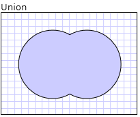
次の例では、CombinedGeometry が Xor の結合モードを指定して定義されています。 Geometry1 と Geometry2 は両方とも同じ半径の円として定義されますが、中心は 50 オフセットされています。
<Path Stroke="Black" StrokeThickness="1" Fill="#CCCCFF">
  <Path.Data>

    <!-- Combines two geometries using the XOR combine mode. -->
    <CombinedGeometry GeometryCombineMode="Xor">
      <CombinedGeometry.Geometry1>
        <EllipseGeometry RadiusX="50" RadiusY="50" Center="75,75" />
      </CombinedGeometry.Geometry1>
      <CombinedGeometry.Geometry2>
        <EllipseGeometry RadiusX="50" RadiusY="50" Center="125,75" />
      </CombinedGeometry.Geometry2>
    </CombinedGeometry>
  </Path.Data>
</Path>
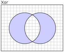
その他の例については、「方法 : 複合図形を作成する」と「方法 : 結合したジオメトリを作成する」をご覧ください。
Freezable 機能
Geometry クラスは Freezable クラスを継承するため、いくつかの特殊な機能を備えています。つまり、Geometry オブジェクトを XAML リソースとして宣言すること、複数のオブジェクト間で共有すること、読み取り専用にしてパフォーマンスを高めること、複製すること、スレッド セーフにすることができます。 Freezable オブジェクトで提供されるさまざまな機能について詳しくは、「Freezable オブジェクトの概要」をご覧ください。
その他のジオメトリ機能
Geometry クラスには、次のような便利なユーティリティ メソッドも用意されています。
FillContains - ジオメトリに別の Geometry が含まれているかどうかを判断します。
StrokeContains - 指定された点が Geometry のストロークに含まれているかどうかを判断します。
メソッドの完全な一覧については、Geometry クラスを参照してください。
関連項目
.NET Desktop feedback
