SkiaSharp 位圖並排
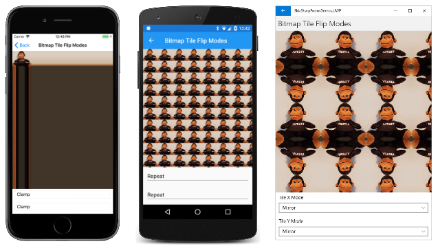
如您在前兩篇文章中所見,類別 SKShader 可以建立線性或圓形漸層。 本文著重於 SKShader 使用位圖來磚區域的物件。 位圖可以水平和垂直重複,其原始方向或水準和垂直翻轉。 翻轉可避免磚之間的不連續:
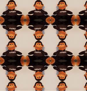
建立這個著色器的靜態SKShader.CreateBitmap方法具有 參數和兩個SKBitmapSKShaderTileMode列舉成員:
public static SKShader CreateBitmap (SKBitmap src, SKShaderTileMode tmx, SKShaderTileMode tmy)
這兩個參數表示用於水準並排和垂直並排的模式。 這是與漸層方法一起使用的相同 SKShaderTileMode 列舉。
CreateBitmap多載包含SKMatrix在磚位圖上執行轉換的自變數:
public static SKShader CreateBitmap (SKBitmap src, SKShaderTileMode tmx, SKShaderTileMode tmy, SKMatrix localMatrix)
本文包含數個搭配磚位圖使用此矩陣轉換的範例。
探索磚模式
範例的 [著色器] 和其他 [效果] 頁面的 [點陣圖圖並排圖] 區段中的第一個程式會示範這兩SKShaderTileMode個自變數的效果。 位圖磚翻轉模式 XAML 檔案會具現化 和SKCanvasView兩Picker個SKShaderTilerMode檢視,讓您選取水準和垂直並排的值。 請注意,成員的 SKShaderTileMode 陣列定義於 Resources 區段中:
<?xml version="1.0" encoding="utf-8" ?>
<ContentPage xmlns="http://xamarin.com/schemas/2014/forms"
             xmlns:x="http://schemas.microsoft.com/winfx/2009/xaml"
             xmlns:skia="clr-namespace:SkiaSharp;assembly=SkiaSharp"
             xmlns:skiaforms="clr-namespace:SkiaSharp.Views.Forms;assembly=SkiaSharp.Views.Forms"
             x:Class="SkiaSharpFormsDemos.Effects.BitmapTileFlipModesPage"
             Title="Bitmap Tile Flip Modes">

    <ContentPage.Resources>
        <x:Array x:Key="tileModes"
                 Type="{x:Type skia:SKShaderTileMode}">
            <x:Static Member="skia:SKShaderTileMode.Clamp" />
            <x:Static Member="skia:SKShaderTileMode.Repeat" />
            <x:Static Member="skia:SKShaderTileMode.Mirror" />
        </x:Array>
    </ContentPage.Resources>

    <StackLayout>
        <skiaforms:SKCanvasView x:Name="canvasView"
                                VerticalOptions="FillAndExpand"
                                PaintSurface="OnCanvasViewPaintSurface" />

        <Picker x:Name="xModePicker"
                Title="Tile X Mode"
                Margin="10, 0"
                ItemsSource="{StaticResource tileModes}"
                SelectedIndex="0"
                SelectedIndexChanged="OnPickerSelectedIndexChanged" />

        <Picker x:Name="yModePicker"
                Title="Tile Y Mode"
                Margin="10, 10"
                ItemsSource="{StaticResource tileModes}"
                SelectedIndex="0"
                SelectedIndexChanged="OnPickerSelectedIndexChanged" />

    </StackLayout>
</ContentPage>
程序代碼後置檔案的建構函式會在顯示猴子坐的點陣圖資源中載入。 它會先使用 ExtractSubset 的 方法來 SKBitmap 裁剪影像,讓頭部和腳觸碰位圖的邊緣。 建構函式接著會使用 Resize 方法來建立大小一半的另一個點陣圖。 這些變更會讓點陣圖更適合並排:
public partial class BitmapTileFlipModesPage : ContentPage
{
    SKBitmap bitmap;

    public BitmapTileFlipModesPage ()
    {
        InitializeComponent ();

        SKBitmap origBitmap = BitmapExtensions.LoadBitmapResource(
            GetType(), "SkiaSharpFormsDemos.Media.SeatedMonkey.jpg");

        // Define cropping rect
        SKRectI cropRect = new SKRectI(5, 27, 296, 260);

        // Get the cropped bitmap
        SKBitmap croppedBitmap = new SKBitmap(cropRect.Width, cropRect.Height);
        origBitmap.ExtractSubset(croppedBitmap, cropRect);

        // Resize to half the width and height
        SKImageInfo info = new SKImageInfo(cropRect.Width / 2, cropRect.Height / 2);
        bitmap = croppedBitmap.Resize(info, SKBitmapResizeMethod.Box);
    }

    void OnPickerSelectedIndexChanged(object sender, EventArgs args)
    {
        canvasView.InvalidateSurface();
    }

    void OnCanvasViewPaintSurface(object sender, SKPaintSurfaceEventArgs args)
    {
        SKImageInfo info = args.Info;
        SKSurface surface = args.Surface;
        SKCanvas canvas = surface.Canvas;

        canvas.Clear();

        // Get tile modes from Pickers
        SKShaderTileMode xTileMode =
            (SKShaderTileMode)(xModePicker.SelectedIndex == -1 ?
                                        0 : xModePicker.SelectedItem);
        SKShaderTileMode yTileMode =
            (SKShaderTileMode)(yModePicker.SelectedIndex == -1 ?
                                        0 : yModePicker.SelectedItem);

        using (SKPaint paint = new SKPaint())
        {
            paint.Shader = SKShader.CreateBitmap(bitmap, xTileMode, yTileMode);
            canvas.DrawRect(info.Rect, paint);
        }
    }
}
處理程式 PaintSurface 會 SKShaderTileMode 從兩 Picker 個檢視取得設定,並根據位圖和這兩個 SKShader 值建立 物件。 此著色器用來填滿畫布:
左側的 iOS 畫面會顯示 預設值 SKShaderTileMode.Clamp的效果。 位圖位於左上角。 在點陣圖下方,圖元的底部數據列會一路重複。 點陣圖右邊,圖元最右邊的數據行會一路重複。 畫布的其餘部分會以點陣圖右下角的深棕色圖元著色。 應該很明顯, Clamp 選項幾乎永遠不會搭配位圖並排使用!
中央的Android畫面會顯示這兩個自變數的結果 SKShaderTileMode.Repeat 。 磚會水準和垂直重複。 通用 Windows 平台 畫面會顯示 SKShaderTileMode.Mirror。 磚會重複,但會以水平和垂直方式翻轉。 此選項的優點是磚之間沒有不連續。
請記住,您可以針對水平和垂直重複使用不同的選項。 您可以將 指定 SKShaderTileMode.Mirror 為 的第二個自變數, CreateBitmap 但 SKShaderTileMode.Repeat 指定為第三個自變數。 在每一排,猴子仍然在正常圖像和鏡子圖像之間交替,但沒有一隻猴子倒置。
圖樣背景
位圖並排常用來從相對較小的位圖建立圖樣背景。 傳統範例是磚牆。
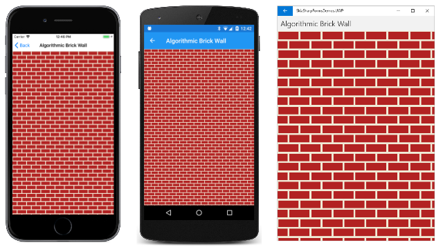
[ 演算法磚牆 ] 頁面會建立一個小型點陣圖,類似於整塊磚和兩半的磚塊,並以迫擊炮分隔。 由於此磚也會用於下一個範例中,所以它是由靜態建構函式所建立,並以靜態屬性公開:
public class AlgorithmicBrickWallPage : ContentPage
{
    static AlgorithmicBrickWallPage()
    {
        const int brickWidth = 64;
        const int brickHeight = 24;
        const int morterThickness = 6;
        const int bitmapWidth = brickWidth + morterThickness;
        const int bitmapHeight = 2 * (brickHeight + morterThickness);

        SKBitmap bitmap = new SKBitmap(bitmapWidth, bitmapHeight);

        using (SKCanvas canvas = new SKCanvas(bitmap))
        using (SKPaint brickPaint = new SKPaint())
        {
            brickPaint.Color = new SKColor(0xB2, 0x22, 0x22);

            canvas.Clear(new SKColor(0xF0, 0xEA, 0xD6));
            canvas.DrawRect(new SKRect(morterThickness / 2,
                                       morterThickness / 2,
                                       morterThickness / 2 + brickWidth,
                                       morterThickness / 2 + brickHeight),
                                       brickPaint);

            int ySecondBrick = 3 * morterThickness / 2 + brickHeight;

            canvas.DrawRect(new SKRect(0,
                                       ySecondBrick,
                                       bitmapWidth / 2 - morterThickness / 2,
                                       ySecondBrick + brickHeight),
                                       brickPaint);

            canvas.DrawRect(new SKRect(bitmapWidth / 2 + morterThickness / 2,
                                       ySecondBrick,
                                       bitmapWidth,
                                       ySecondBrick + brickHeight),
                                       brickPaint);
        }

        // Save as public property for other programs
        BrickWallTile = bitmap;
    }

    public static SKBitmap BrickWallTile { private set; get; }
    ···
}
結果點陣圖寬 70 像素,高 60 像素:

[演算法磚牆] 頁面的其餘部分會建立物件SKShader,以水平和垂直方式重複此影像:
public class AlgorithmicBrickWallPage : ContentPage
{
    ···
    public AlgorithmicBrickWallPage ()
    {
        Title = "Algorithmic Brick Wall";

        // Create SKCanvasView
        SKCanvasView canvasView = new SKCanvasView();
        canvasView.PaintSurface += OnCanvasViewPaintSurface;
        Content = canvasView;
    }

    void OnCanvasViewPaintSurface(object sender, SKPaintSurfaceEventArgs args)
    {
        SKImageInfo info = args.Info;
        SKSurface surface = args.Surface;
        SKCanvas canvas = surface.Canvas;

        canvas.Clear();

        using (SKPaint paint = new SKPaint())
        {
            // Create bitmap tiling
            paint.Shader = SKShader.CreateBitmap(BrickWallTile,
                                                 SKShaderTileMode.Repeat,
                                                 SKShaderTileMode.Repeat);
            // Draw background
            canvas.DrawRect(info.Rect, paint);
        }
    }
}
結果如下︰
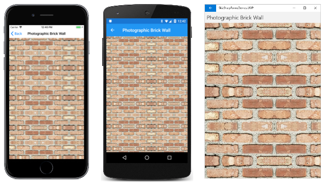
您可能更喜歡更現實的東西。 在這種情況下,您可以拍攝實際磚牆的照片,然後裁剪它。 此點陣圖寬 300 像素,高度為 150 像素:
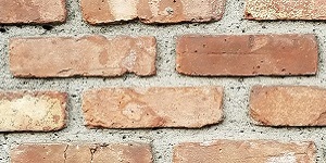
此點陣圖用於 攝影磚牆 頁面:
public class PhotographicBrickWallPage : ContentPage
{
    SKBitmap bitmap = BitmapExtensions.LoadBitmapResource(
                        typeof(PhotographicBrickWallPage),
                        "SkiaSharpFormsDemos.Media.BrickWallTile.jpg");

    public PhotographicBrickWallPage()
    {
        Title = "Photographic Brick Wall";

        SKCanvasView canvasView = new SKCanvasView();
        canvasView.PaintSurface += OnCanvasViewPaintSurface;
        Content = canvasView;
    }

    void OnCanvasViewPaintSurface(object sender, SKPaintSurfaceEventArgs args)
    {
        SKImageInfo info = args.Info;
        SKSurface surface = args.Surface;
        SKCanvas canvas = surface.Canvas;

        canvas.Clear();

        using (SKPaint paint = new SKPaint())
        {
            // Create bitmap tiling
            paint.Shader = SKShader.CreateBitmap(bitmap,
                                                 SKShaderTileMode.Mirror,
                                                 SKShaderTileMode.Mirror);
            // Draw background
            canvas.DrawRect(info.Rect, paint);
        }
    }
}
請注意,的SKShaderTileModeCreateBitmap自變數都是 Mirror。 當您使用從真實世界影像建立的磚時,通常有必要使用此選項。 鏡像磚可避免不連續:
需要某些工作才能取得磚的適當點圖。 這塊磚效果不好,因為較深的磚塊太突出了。 它經常出現在重複的影像中,顯示這個磚牆是從較小的位圖建構的。
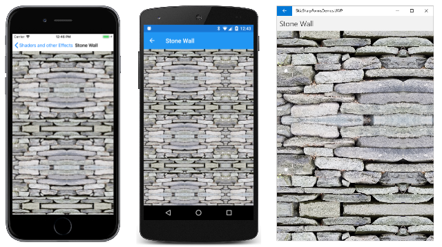
範例的 Media 資料夾也包含石牆的這個影像:
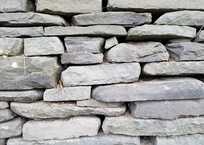
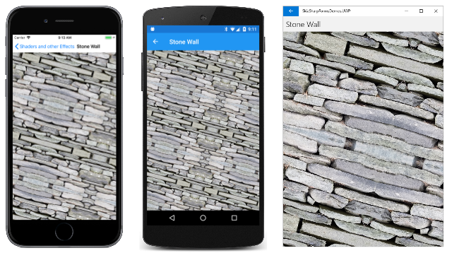
不過,原始點圖對於磚來說有點太大。 它可以重設大小,但 SKShader.CreateBitmap 方法也可以套用轉換來調整磚的大小。 這個選項會在 [石牆 ] 頁面中示範:
public class StoneWallPage : ContentPage
{
    SKBitmap bitmap = BitmapExtensions.LoadBitmapResource(
                        typeof(StoneWallPage),
                        "SkiaSharpFormsDemos.Media.StoneWallTile.jpg");

    public StoneWallPage()
    {
        Title = "Stone Wall";

        SKCanvasView canvasView = new SKCanvasView();
        canvasView.PaintSurface += OnCanvasViewPaintSurface;
        Content = canvasView;
    }

    void OnCanvasViewPaintSurface(object sender, SKPaintSurfaceEventArgs args)
    {
        SKImageInfo info = args.Info;
        SKSurface surface = args.Surface;
        SKCanvas canvas = surface.Canvas;

        canvas.Clear();

        using (SKPaint paint = new SKPaint())
        {
            // Create scale transform
            SKMatrix matrix = SKMatrix.MakeScale(0.5f, 0.5f);

            // Create bitmap tiling
            paint.Shader = SKShader.CreateBitmap(bitmap,
                                                 SKShaderTileMode.Mirror,
                                                 SKShaderTileMode.Mirror,
                                                 matrix);
            // Draw background
            canvas.DrawRect(info.Rect, paint);
        }
    }
}
系統會建立一個 SKMatrix 值,以將影像調整為其原始大小的一半:
轉換是否在方法中使用的 CreateBitmap 原始點陣圖上運作? 還是會轉換圖格的結果陣列?
回答此問題的簡單方法是在轉換中包含輪替:
SKMatrix matrix = SKMatrix.MakeScale(0.5f, 0.5f);
SKMatrix.PostConcat(ref matrix, SKMatrix.MakeRotationDegrees(15));
如果轉換套用至個別磚,則應該旋轉磚的每個重複影像,結果會包含許多不連續。 但從此螢幕快照中很明顯,磚的複合陣列已轉換:
在圖格對齊一節中,您會看到套用至著色器的翻譯轉換範例。
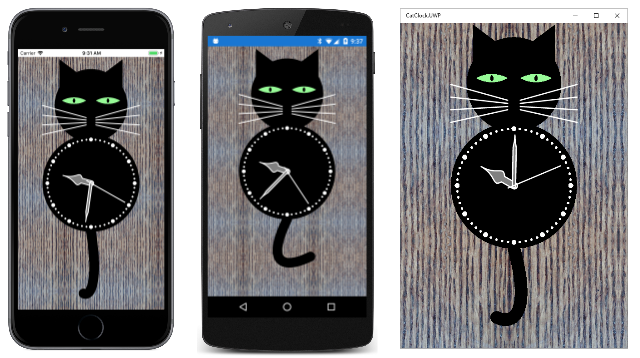
此範例會根據這個 240 像素的方形點圖,使用位圖並排來模擬木粒背景:
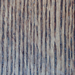
這是一張伍德地板的照片。 這個選項 SKShaderTileMode.Mirror 可讓它顯示為更大的木材區域:
磚對齊方式
到目前為止顯示的所有範例都使用 所 SKShader.CreateBitmap 建立的著色器來涵蓋整個畫布。 在大部分情況下,您將使用位圖圖並排來提出較小的區域,或更很少用於填滿厚線條的內部。 以下是用於較小矩形的攝影磚牆磚:
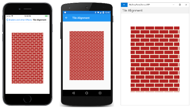
這看起來可能很好,或者可能不是。 也許您感到不安的是,磚狀圖樣不會從矩形左上角的完整磚塊開始。 這是因為著色器會與畫布對齊,而不是它們裝飾的圖形物件。
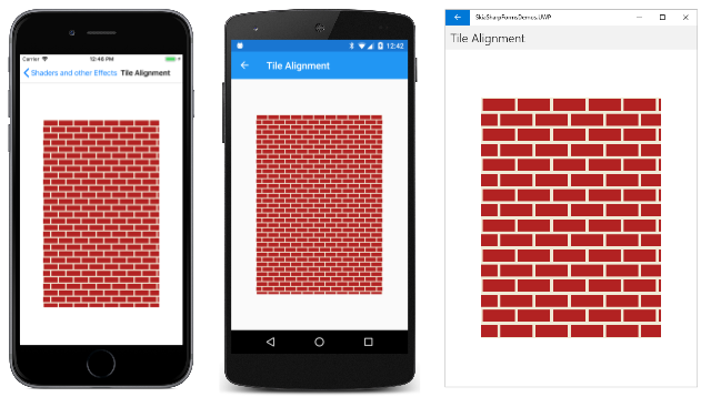
修正很簡單。 根據翻譯轉換建立 SKMatrix 值。 轉換會有效地將磚圖樣移轉至您想要對齊磚左上角的點。 此方法會在 [磚對齊 ] 頁面中示範,該頁面會建立上面所示未對齊磚的影像:
public class TileAlignmentPage : ContentPage
{
    bool isAligned;

    public TileAlignmentPage()
    {
        Title = "Tile Alignment";

        SKCanvasView canvasView = new SKCanvasView();
        canvasView.PaintSurface += OnCanvasViewPaintSurface;

        // Add tap handler
        TapGestureRecognizer tap = new TapGestureRecognizer();
        tap.Tapped += (sender, args) =>
        {
            isAligned ^= true;
            canvasView.InvalidateSurface();
        };
        canvasView.GestureRecognizers.Add(tap);

        Content = canvasView;
    }

    void OnCanvasViewPaintSurface(object sender, SKPaintSurfaceEventArgs args)
    {
        SKImageInfo info = args.Info;
        SKSurface surface = args.Surface;
        SKCanvas canvas = surface.Canvas;

        canvas.Clear();

        using (SKPaint paint = new SKPaint())
        {
            SKRect rect = new SKRect(info.Width / 7,
                                     info.Height / 7,
                                     6 * info.Width / 7,
                                     6 * info.Height / 7);

            // Get bitmap from other program
            SKBitmap bitmap = AlgorithmicBrickWallPage.BrickWallTile;

            // Create bitmap tiling
            if (!isAligned)
            {
                paint.Shader = SKShader.CreateBitmap(bitmap,
                                                     SKShaderTileMode.Repeat,
                                                     SKShaderTileMode.Repeat);
            }
            else
            {
                SKMatrix matrix = SKMatrix.MakeTranslation(rect.Left, rect.Top);

                paint.Shader = SKShader.CreateBitmap(bitmap,
                                                     SKShaderTileMode.Repeat,
                                                     SKShaderTileMode.Repeat,
                                                     matrix);
            }

            // Draw rectangle
            canvas.DrawRect(rect, paint);
        }
    }
}
[ 磚對齊] 頁面包含 TapGestureRecognizer。 點選或按兩下畫面,程式會使用 SKMatrix 自變數切換至 SKShader.CreateBitmap 方法。 此轉換會移動模式,讓左上角包含完整的磚塊:
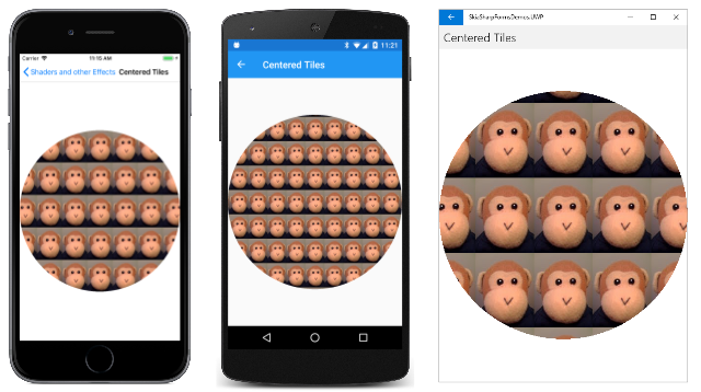
您也可以使用這項技術,確保磚位圖圖樣置中位於繪製的區域。 在 [ 置中磚 ] 頁面中, PaintSurface 處理程式會先計算座標,就好像要在畫布中央顯示單一位圖一樣。 然後,它會使用這些座標來建立的 SKShader.CreateBitmap轉譯轉換。 此轉換會轉移整個模式,讓磚置中:
public class CenteredTilesPage : ContentPage
{
    SKBitmap bitmap = BitmapExtensions.LoadBitmapResource(
                        typeof(CenteredTilesPage),
                        "SkiaSharpFormsDemos.Media.monkey.png");

    public CenteredTilesPage ()
    {
        Title = "Centered Tiles";

        SKCanvasView canvasView = new SKCanvasView();
        canvasView.PaintSurface += OnCanvasViewPaintSurface;
        Content = canvasView;
    }

    void OnCanvasViewPaintSurface(object sender, SKPaintSurfaceEventArgs args)
    {
        SKImageInfo info = args.Info;
        SKSurface surface = args.Surface;
        SKCanvas canvas = surface.Canvas;

        canvas.Clear();

        // Find coordinates to center bitmap in canvas...
        float x = (info.Width - bitmap.Width) / 2f;
        float y = (info.Height - bitmap.Height) / 2f;

        using (SKPaint paint = new SKPaint())
        {
            // ... but use them to create a translate transform
            SKMatrix matrix = SKMatrix.MakeTranslation(x, y);
            paint.Shader = SKShader.CreateBitmap(bitmap,
                                                 SKShaderTileMode.Repeat,
                                                 SKShaderTileMode.Repeat,
                                                 matrix);

            // Use that tiled bitmap pattern to fill a circle
            canvas.DrawCircle(info.Rect.MidX, info.Rect.MidY,
                              Math.Min(info.Width, info.Height) / 2,
                              paint);
        }
    }
}
處理程式會 PaintSurface 藉由在畫布中央繪製圓形來結束。 果然,其中一個磚正好位於圓形的中心,而其他磚則以對稱模式排列:
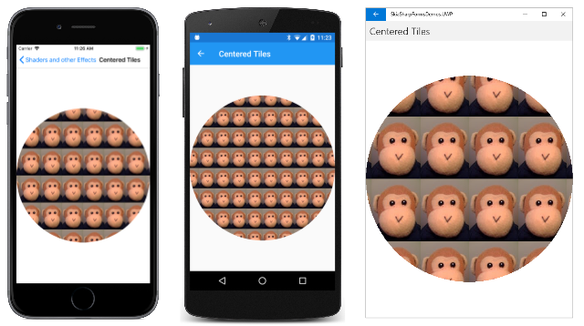
另一個置中方法實際上會比較容易一點。 您可以置中並排圖的角落,而不是建構將磚放在中央的平移轉換。 在呼叫中 SKMatrix.MakeTranslation ,使用畫布中央的自變數:
SKMatrix matrix = SKMatrix.MakeTranslation(info.Rect.MidX, info.Rect.MidY);
模式仍會置中且對稱,但中央沒有磚:
透過旋轉簡化
有時候在 SKShader.CreateBitmap 方法中使用旋轉轉換可以簡化點圖磚。 嘗試定義鏈結柵欄的磚時,這會變得很明顯。 ChainLinkTile.cs檔案會建立此處顯示的磚(有粉紅色的背景,以便清楚起見):
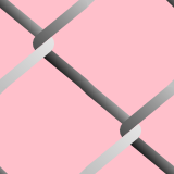
磚必須包含兩個連結,讓程式代碼將磚分成四個象限。 左上方和右下象限相同,但不完整。 電線幾乎沒有小聲點,必須在右上方和左下象限中用一些額外的繪圖來處理。 執行這項工作的檔案長度為174行。
事實證明,建立此磚會更容易:
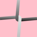
如果點圖磚著色器旋轉 90 度,視覺效果幾乎相同。
建立更容易鏈結連結磚的程序代碼是 [鏈結磚] 頁面的一部分。 建構函式會根據程序執行所在的裝置類型來決定磚大小,然後呼叫 CreateChainLinkTile,其會使用線條、路徑和漸層著色器在位圖上繪製:
public class ChainLinkFencePage : ContentPage
{
    ···
    SKBitmap tileBitmap;

    public ChainLinkFencePage ()
    {
        Title = "Chain-Link Fence";

        // Create bitmap for chain-link tiling
        int tileSize = Device.Idiom == TargetIdiom.Desktop ? 64 : 128;
        tileBitmap = CreateChainLinkTile(tileSize);

        SKCanvasView canvasView = new SKCanvasView();
        canvasView.PaintSurface += OnCanvasViewPaintSurface;
        Content = canvasView;
    }

    SKBitmap CreateChainLinkTile(int tileSize)
    {
        tileBitmap = new SKBitmap(tileSize, tileSize);
        float wireThickness = tileSize / 12f;

        using (SKCanvas canvas = new SKCanvas(tileBitmap))
        using (SKPaint paint = new SKPaint())
        {
            canvas.Clear();
            paint.Style = SKPaintStyle.Stroke;
            paint.StrokeWidth = wireThickness;
            paint.IsAntialias = true;

            // Draw straight wires first
            paint.Shader = SKShader.CreateLinearGradient(new SKPoint(0, 0),
                                                         new SKPoint(0, tileSize),
                                                         new SKColor[] { SKColors.Silver, SKColors.Black },
                                                         new float[] { 0.4f, 0.6f },
                                                         SKShaderTileMode.Clamp);

            canvas.DrawLine(0, tileSize / 2,
                            tileSize / 2, tileSize / 2 - wireThickness / 2, paint);

            canvas.DrawLine(tileSize, tileSize / 2,
                            tileSize / 2, tileSize / 2 + wireThickness / 2, paint);

            // Draw curved wires
            using (SKPath path = new SKPath())
            {
                path.MoveTo(tileSize / 2, 0);
                path.LineTo(tileSize / 2 - wireThickness / 2, tileSize / 2);
                path.ArcTo(wireThickness / 2, wireThickness / 2,
                           0,
                           SKPathArcSize.Small,
                           SKPathDirection.CounterClockwise,
                           tileSize / 2, tileSize / 2 + wireThickness / 2);

                paint.Shader = SKShader.CreateLinearGradient(new SKPoint(0, 0),
                                                             new SKPoint(0, tileSize),
                                                             new SKColor[] { SKColors.Silver, SKColors.Black },
                                                             null,
                                                             SKShaderTileMode.Clamp);
                canvas.DrawPath(path, paint);

                path.Reset();
                path.MoveTo(tileSize / 2, tileSize);
                path.LineTo(tileSize / 2 + wireThickness / 2, tileSize / 2);
                path.ArcTo(wireThickness / 2, wireThickness / 2,
                           0,
                           SKPathArcSize.Small,
                           SKPathDirection.CounterClockwise,
                           tileSize / 2, tileSize / 2 - wireThickness / 2);

                paint.Shader = SKShader.CreateLinearGradient(new SKPoint(0, 0),
                                                             new SKPoint(0, tileSize),
                                                             new SKColor[] { SKColors.White, SKColors.Silver },
                                                             null,
                                                             SKShaderTileMode.Clamp);
                canvas.DrawPath(path, paint);
            }
            return tileBitmap;
        }
    }
    ···
}
除了電線外,磚是透明的,這表示您可以在其他項目上顯示它。 程式會在其中一個點陣圖資源中載入、顯示它以填滿畫布,然後繪製頂端的著色器:
public class ChainLinkFencePage : ContentPage
{
    SKBitmap monkeyBitmap = BitmapExtensions.LoadBitmapResource(
        typeof(ChainLinkFencePage), "SkiaSharpFormsDemos.Media.SeatedMonkey.jpg");
    ···

    void OnCanvasViewPaintSurface(object sender, SKPaintSurfaceEventArgs args)
    {
        SKImageInfo info = args.Info;
        SKSurface surface = args.Surface;
        SKCanvas canvas = surface.Canvas;

        canvas.Clear();

        canvas.DrawBitmap(monkeyBitmap, info.Rect, BitmapStretch.UniformToFill,
                            BitmapAlignment.Center, BitmapAlignment.Start);

        using (SKPaint paint = new SKPaint())
        {
            paint.Shader = SKShader.CreateBitmap(tileBitmap,
                                                 SKShaderTileMode.Repeat,
                                                 SKShaderTileMode.Repeat,
                                                 SKMatrix.MakeRotationDegrees(45));
            canvas.DrawRect(info.Rect, paint);
        }
    }
}
請注意,著色器會旋轉 45 度,因此方向就像真正的鏈結柵欄一樣:
以動畫顯示位圖磚
您可以建立矩陣轉換的動畫效果,以建立整個點陣圖磚模式的動畫效果。 也許您想要模式水準或垂直移動或兩者。 您可以藉由根據移動座標建立翻譯轉換來執行此動作。
您也可以在小型點陣圖上繪製,或以每秒 60 次的速率操作位圖的圖元位。 然後,該位圖可用於並排顯示,而且整個並排圖模式似乎可以產生動畫效果。
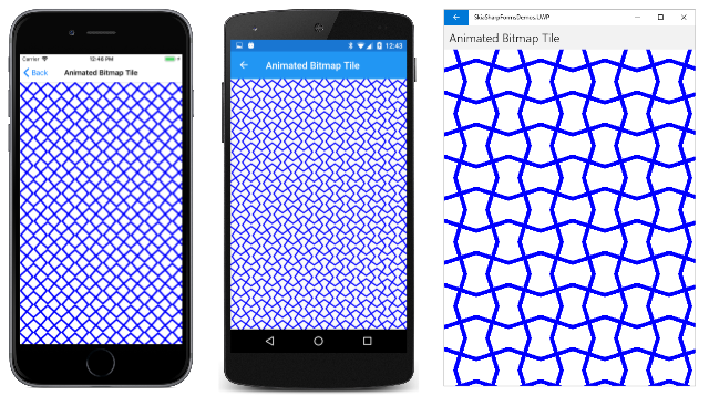
[ 動畫點圖磚 ] 頁面示範此方法。 位圖會具現化為 64 像素平方的欄位。 建構函式會呼叫 DrawBitmap 來提供其初始外觀。 angle如果欄位為零(如同第一次呼叫 方法時),則點陣圖會包含兩行交叉為 X。不論值為何angle,這些線條的長度都足以一律到達位圖的邊緣:
public class AnimatedBitmapTilePage : ContentPage
{
    const int SIZE = 64;

    SKCanvasView canvasView;
    SKBitmap bitmap = new SKBitmap(SIZE, SIZE);
    float angle;
    ···

    public AnimatedBitmapTilePage ()
    {
        Title = "Animated Bitmap Tile";

        // Initialize bitmap prior to animation
        DrawBitmap();

        // Create SKCanvasView
        canvasView = new SKCanvasView();
        canvasView.PaintSurface += OnCanvasViewPaintSurface;
        Content = canvasView;
    }
    ···
    void DrawBitmap()
    {
        using (SKCanvas canvas = new SKCanvas(bitmap))
        using (SKPaint paint = new SKPaint())
        {
            paint.Style = SKPaintStyle.Stroke;
            paint.Color = SKColors.Blue;
            paint.StrokeWidth = SIZE / 8;

            canvas.Clear();
            canvas.Translate(SIZE / 2, SIZE / 2);
            canvas.RotateDegrees(angle);
            canvas.DrawLine(-SIZE, -SIZE, SIZE, SIZE, paint);
            canvas.DrawLine(-SIZE, SIZE, SIZE, -SIZE, paint);
        }
    }
    ···
}
動畫額外負荷會在 和 OnAppearing OnDisappearing 覆寫中發生。 OnTimerTick方法會angle每隔 10 秒以動畫顯示 0 度到 360 度的值,以旋轉點陣圖內的 X 圖:
public class AnimatedBitmapTilePage : ContentPage
{
    ···
    // For animation
    bool isAnimating;
    Stopwatch stopwatch = new Stopwatch();
    ···

    protected override void OnAppearing()
    {
        base.OnAppearing();

        isAnimating = true;
        stopwatch.Start();
        Device.StartTimer(TimeSpan.FromMilliseconds(16), OnTimerTick);
    }

    protected override void OnDisappearing()
    {
        base.OnDisappearing();

        stopwatch.Stop();
        isAnimating = false;
    }

    bool OnTimerTick()
    {
        const int duration = 10;     // seconds
        angle = (float)(360f * (stopwatch.Elapsed.TotalSeconds % duration) / duration);
        DrawBitmap();
        canvasView.InvalidateSurface();

        return isAnimating;
    }
    ···
}
由於 X 圖的對稱性,這與每 2.5 秒將值從 0 度旋轉 angle 到 90 度相同。
處理程式 PaintSurface 會從點陣圖建立著色器,並使用繪製物件來著色整個畫布:
public class AnimatedBitmapTilePage : ContentPage
{
    ···
    void OnCanvasViewPaintSurface(object sender, SKPaintSurfaceEventArgs args)
    {
        SKImageInfo info = args.Info;
        SKSurface surface = args.Surface;
        SKCanvas canvas = surface.Canvas;

        canvas.Clear();

        using (SKPaint paint = new SKPaint())
        {
            paint.Shader = SKShader.CreateBitmap(bitmap,
                                                 SKShaderTileMode.Mirror,
                                                 SKShaderTileMode.Mirror);
            canvas.DrawRect(info.Rect, paint);
        }
    }
}
這些 SKShaderTileMode.Mirror 選項可確保每個點陣圖中 X 的手臂與相鄰點陣圖中的 X 聯結,以建立整體動畫模式,看起來比簡單動畫所建議的要複雜得多:
