Fun(ctional) graphics in C#!
Graphics programming often involves customizing and combining well known techniques as mathematic formulas and algorithms related to geometry, lighting, physics, and so on. For performance and architecture reasons, realizing these formulas in a real programming involves drastic transformations that results in code that is hard to read and write. For example, multiple graphics techniques are encoded into low-level pixel and vertex shader code in way that renders them unrecognizable.
One solution is to encode graphic techniques in a high-level functional programming language, where functions allow us to effectively represent, combine, and manipulate graphic techniques. Take for example lighting computations that can be represented as a function Position3D –> Normal3D –> InputColor –> ResultColor, which can then be combined via addition: take two lighting computations l1 and l2, where a succinct l1 + l2 expands to p –> n –> c –> l1(p)(n)(c) + l2(p)(n)(c). As graphics is math-intensive, it benefits dramatically from function representations.
Unfortunately, their are a couple of drawbacks to this approach. First, the execution of a functional program is drastically slower than imperative code. However, as most graphics computations are moving to GPUs via memory-restricted shader code, this problem can be solved by generating shader code from functional programs. Such is the approach taken by Conal Elliott’s Haskell-hosted Vertigo library done at MSR. In Vertigo, geometries can be expressed as parametric surfaces, surface normals for lighting are computed via symbolic differentiation. The second drawback is more one of familiarity: the techniques seem to require abandoning our existing mainstream languages and tools for dramatically different and less familiar languages such as Haskell. However, while functional programming definitely benefits from functional languages, functional programming techniques can definitely be applied in more familiar languages. As a mainstream language, C# even provides a lambda construct to support programmers who want to dabble in functional programming; e.g., by using LINQ to query databases.
I’m implementing a functional graphics library in Bling for C#. Bling supports the creation and composition of expression trees as seemingly normal C# expressions, allowing us to easily compose code in a high level language and then ship the result to the GPU as a vertex or pixel shader. This allows us, among other things, to support a style of programming very similar to how Vertigo is used in Haskell. For example, consider the definition of a sphere parametric surface in Bling:
 public static readonly PSurface Sphere = new PSurface((PointBl p) => {
  PointBl sin = p.SinU;
  PointBl cos = p.CosU;
  return new Point3DBl(sin[0] * cos[1], sin[0] * sin[1], cos[0]);
});
PSurface is a wrapper around a function from PointBl to Point3DBl, which are wrapper types around point (R2) and 3D point (R3) expression trees. SinU and CosU define scaled sine and cosine values over points between [0,0] and [1,1] by using the coordinates as percentage for 2PI angles. Rendering a sphere in Bling is simply a matter of creating some light and defining how many vertices we want to sample in the resulting vertex buffer:
 PSurface Surface = Geometries.Sphere;
DirectionalLightBl dirLight = new DirectionalLightBl() {
  Direction = new Point3DBl(0, 0, 1),
  Color = Colors.White,
};
ParametricKeys SurfaceKeys = new ParametricKeys(200, 200);
Device.Render(SurfaceKeys, (IntBl n, PointBl uv, IVertex vertex) => {
  vertex.Position = (Surface * (world * view * project))[uv]; ;
  Point3DBl norm = (Point3DBl)(Surface.Normals[uv] * world).Normalize;
  Point3DBl usePosition = (Point3DBl)((Surface[uv] * (world)));
  vertex.Color = dirLight.Diffuse()[usePosition, norm](n.SelectColor());
});
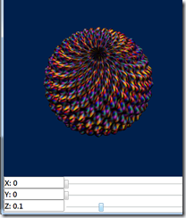
where world, view, and project are standard 4x4 matrices used in translating position in 3D scenes. This code creates a directional light coming from the bottom (reused from WPF 3D no less!) and defines a set of surface keys over 200 by 200 vertices, meaning 40,000 vertices are sampled in the rendered sphere. The light is applied to the sphere in a render function using a world transformed position of each vertex along with a world transformed normal that is automatically computed via the derivative of the parametric surface. The color for each vertex is selected based on the vertex index, leading to a nice spiral pattern in the sphere that also gives us an idea of vertex topology. Here is the result:
As described in the Vertigo paper, interesting geometries can also be formed from surfaces via displacement by height fields. Copying the examples in the vertigo paper, consider an eggcrate height field that whose definition in Bling has a simple structure similar to sphere:
 public static readonly HeightField EggCrate = new HeightField((PointBl p) => {
  p = p.SinCosU;
  return p.X * p.Y;
});
The displacement method on surfaces is then defined as follows:
 public PSurface Displace(Func<PointBl, DoubleBl> HeightField) {
  return new PSurface((PointBl p) =>
    this[p] + Normals[p] * HeightField(p));
}
As with lighting computations, surface normals are used to determine the proper direction in which to apply the height field. We can then apply the egg crate height field to a sphere as follows:
 PSurface Surface = Geometries.Sphere.
  Displace((Geometries.EggCrate.Frequency(20d).Magnitude(sliderZ.Value * .5)));
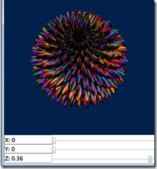
The frequency and magnitude of a height field are adjusted via methods that have one line implementations (again, this is described in the Vertigo paper). One twist is that we control the magnitude by a slider (Z), which is a standard WPF slider with a value dependency property. Now, by moving the slider up, the sphere becomes deformed via the egg crate height field:
Moving the slider even farther up, the sphere becomes spiky:
The change in deformation occurs in real time, so we see a smooth animation as the sphere becomes deformed.
Bling will automatically determine what code executes outside of the shader in the form of either uniforms (per-shader external variables) or vertex buffers (per-vertex data). Bling will also determine what code runs in pixel shaders vs. vertex shaders, and will automatically generate vertex input and output structures to accommodate communication between the two kinds of shaders. Bling will also generate code to handle update uniforms and vertex buffers during rendering, requiring absolutely no boilerplate code on behalf of the programmer. Instead, the programmer can just focus on what graphics techniques they want to use, without needing to worry about adapting them to fit on the underlying graphics architecture. For the above example, here is the HLSL code that Bling generates, which is then rendered using Direct3D 10:
1.
float U0;
2.
float4x4 U1;
3.
float4x4 U2;
4.
float3 U3;
5.
float3 U4;
6.
struct VS_Input {
7.
float P0 : POSITION;
8.
float3 P1 : POSITION1;
9.
float3 P2 : POSITION2;
10.
float P3 : NORMAL;
11.
float3 P4 : NORMAL1;
12.
float3 P5 : NORMAL2;
13.
float P6 : NORMAL3;
14.
float3 P7 : NORMAL4;
15.
float3 P8 : NORMAL5;
16.
float4 P9 : COLOR;
17.
};
18.
struct VS_Output {
19.
float4 Pos : SV_Position;
20.
float4 P0 : COLOR;
21.
};
22.
VS_Output VS(VS_Input input) {
23.
VS_Output output = (VS_Output) 0;
24.
float t0_0 = (U0 * input.P0);
25.
float3 t0_1 = t0_0.xxx;
26.
float3 t0_2 = (input.P1 * t0_1);
27.
float3 t0_3 = (input.P2 + t0_2);
28.
float3 t0_4 = t0_3.xyz;
29.
float4 t0_5 = float4(t0_4, 1);
30.
float4 t0_6 = t0_5;
31.
float4 t0_7 = mul(t0_6, U1);
32.
float4 t0_8 = t0_7;
33.
float3 t0_9 = t0_8.xyz;
34.
float3 t0_10 = t0_8.w.xxx;
35.
float3 t0_11 = (t0_9 / t0_10);
36.
float4 t0_12 = float4(t0_11, 1);
37.
float t0_13 = (U0 * input.P3);
38.
float3 t0_14 = t0_13.xxx;
39.
float3 t0_15 = (input.P1 * t0_14);
40.
float3 t0_16 = (t0_1 * input.P4);
41.
float3 t0_17 = (t0_15 + t0_16);
42.
float3 t0_18 = (input.P5 + t0_17);
43.
float3x1 t0_19 = float3x1(t0_18.x, t0_18.y, t0_18.z);
44.
float3 t0_20 = t0_19;
45.
float t0_21 = (U0 * input.P6);
46.
float3 t0_22 = t0_21.xxx;
47.
float3 t0_23 = (input.P1 * t0_22);
48.
float3 t0_24 = (t0_1 * input.P7);
49.
float3 t0_25 = (t0_23 + t0_24);
50.
float3 t0_26 = (input.P8 + t0_25);
51.
float3x1 t0_27 = float3x1(t0_26.x, t0_26.y, t0_26.z);
52.
float3 t0_28 = t0_27;
53.
float3 t0_29 = cross(t0_20, t0_28);
54.
float3 t0_30 = normalize(t0_29);
55.
float3 t0_31 = t0_30.xyz;
56.
float4 t0_32 = float4(t0_31, 1);
57.
float4 t0_33 = t0_32;
58.
float4 t0_34 = mul(t0_33, U2);
59.
float4 t0_35 = t0_34;
60.
float4 t0_36 = normalize(t0_35);
61.
float3 t0_37 = t0_36.xyz;
62.
float3 t0_38 = t0_36.w.xxx;
63.
float3 t0_39 = (t0_37 / t0_38);
64.
float t0_40 = dot(U3, t0_39);
65.
float t0_41 = max(t0_40, 0);
66.
float3 t0_42 = t0_41.xxx;
67.
float3 t0_43 = (U4 * t0_42);
68.
float4 t0_44 = float4(t0_43, 1);
69.
float4 t0_45 = (t0_44 * input.P9);
70.
output.Pos = t0_12;
71.
output.P0 = t0_45;
72.
return output;
73.
}
74.
75.
float4 PS(VS_Output input) : SV_Target {
76.
float4 retV;
77.
retV = input.P0;
78.
return retV;
79.
}
80.
81.
technique10 Render {
82.
pass P0 {
83.
SetVertexShader( CompileShader( vs_4_0, VS() ) );
84.
SetGeometryShader(NULL);
85.
SetPixelShader(CompileShader(ps_4_0, PS()));
86.
}
87.
}
88.
Since the code is auto-generated, it is not very pretty, but it doesn’t have to be. I still need to work on the conversion process to minimize the number of vertex parameters passed in as input, as these are limited to 16 and can easily be exhausted when more external values (e.g., sliders) are added to parameterize geometry and lighting.
The code for this example is currently available in our codeplex SVN repository at https://bling.svn.codeplex.com/svn/Bling3, and I’m currently working on cleaning things up for a new release of Bling (titled Bling 3) that will support rich UI construction in WPF and preliminary support for DirectX 10 (sorry XP users!) as described in this post.


