Avoiding traps in Windows Embedded Studio
[The following article is authored by one of the Windows Embedded MVPs (Most Valuable Professionals). Our MVPs have a heavy background in Embedded systems and are a great repository of information on Windows Embedded products. We’re providing this space on our team blog as a service to our readers by allowing MVPs to share some of their knowledge with the rest of the community.]
As with any tool there are some situations in Windows Embedded Studio new users may find challenging to understand, when they occur for the first time. In this post I have collected the most common ones, hoping to provide some insight into why they happen and how users should react to resolve the issues.
Component visibility
Not all components are displayed using default settings. This is due to fact that components have a visibility property, which corresponds to the minimum visibility setting in the “Advanced” tab in Target Designer options.
The default value here is 1000. To see all available components one should set this option to 100. This is analogous to the altitude a plane is flying at. From high altitude one sees just a few details, while more details become visible when flying low. Even with a minimum visibility set to 100 not all available components are shown. There are still some system components that are not configurable via the UI but will get pulled into a configuration via component dependencies.
Resource information
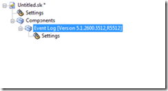
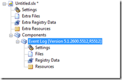
When configuring an image with the default configuration the components display a settings node in the work pane, which gives access to additional options. If the View->Resources menu is enabled, additional nodes appear giving access to files registry keys and other resources of a component.
Before After
Connection problems
Windows Embedded Studio is architected as a team development environment. This means that, even when installed locally, it is using network shares (\\<computer name>\Repositories) to connect to the repositories for copying files during build. Normally this is not a problem, but if no network connection is available and the TCP/IP stack is not running (e.g. when using a standalone laptop) there will be “file not found” error messages during build. The resolution to this problem is quite easy. Install the Microsoft loopback adapter on the development system. This is a virtual network adapter, which keeps the TCP/IP stack up and running even when no network is available. You could change the path of each repository in the Repository tab of Component Database Manager to point to the local address.
Deleting macro components
Macro components are containers for other components. They just store the references to the other components. This is great for creating templates, functionality blocks, et cetera. But, it is important to understand that a macro component can be only used to pull other components into a configuration. It cannot be used to delete them, because the reverse process is not supported. To delete the contents of a macro component from the configuration all the referenced components and the macro component need to be deleted manually.
Components that get added back even after deleting them
Components that keep getting added to a configuration after a dependency check is run, even after they have been manually deleted, are partly related to the macro component issue described above. If a component, which is part of a macro component or a dependency of another component, is deleted it will be pulled in during the next dependency check as long as the component that depends on it or is referencing it is part of the configuration.
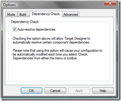
This behavior can be controlled via the Tools->Options dialog in Target Designer.
Uncheck the Auto-resolve dependencies box and the deleted components will stay out of the image. Nevertheless, tasks entries will be generated showing that this dependency was not satisfied. If the component needs not to be part of the image this is absolutely fine.
This setting turns off auto-resolve for additional components you add, as well, which means that these tasks must be resolved manually, if necessary.
Importing components
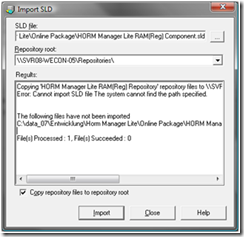
The import of a component definition file (.sld) into the component database is accomplished by using Component Database Manager in Windows Embedded Studio. The process itself is pretty straightforward. Just point the importer to the .sld file und run the import. If this does not work the following message will appear:
People often tend to not look too closely at this output and just read “Succeeded” and move on, which leads to build problems later on. While “Suceeded: 0” is perfect developer logic, it is not the most user-friendly output to display here.
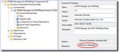
The reason for this error often is that the repository with the binaries related to the component has been created, but was not linked to the component itself in Component Designer, as shown below.
As soon as the Repository property points to the dedicated repository, the import completes with “Succeeded: 1”.
Performance
Although huge improvements have been made to the toolset during its evolution, performance always has been an issue. The reason for this is that Target Designer is using XML to handle its data and this consumes quite a lot of RAM. On development machines with limited resources, RAM pages get swapped to disk after reaching a certain memory threshold, which is a significant performance hit. Therefore putting more than 1GB of RAM into a Windows Embedded Standard development machine is a best practice. If you can afford more, it will not hurt.
Alexander Wechsler
Wechsler Consulting
Technorati Tags: XPe,Standard 2009
Comments
- Anonymous
April 20, 2009
PingBack from http://asp-net-hosting.simplynetdev.com/avoiding-traps-in-windows-embedded-studio/

