在 Windows、Linux 和 macOS 计算机上使用 .NET IoT 库
.NET IoT 库通常用于开发 Raspberry Pi 和其他 IoT 设备的代码。 不过,还可使用它们通过 USB 转串口适配器(例如 FTDI FT232H)为 Windows、Linux 和 macOS 电脑开发代码。 本文介绍如何使用 .NET IoT 库与连接到 FT232H 适配器的设备通信。
提示
本文使用 FTDI FT232H 适配器,但你可以使用 .NET IoT 库支持的任何 USB 转串口适配器,例如 FT2232H、FT4232H 和 FT4222。 有关详细信息,请参阅支持的设备绑定列表。
先决条件
确保已为 USB 转串口适配器安装 D2XX 驱动程序(可在 FTDI 网站上找到)。
注意
插入适配器时,Windows 设备可能会自动安装驱动程序。 检查设备管理器,查看在“通用串行总线控制器”下列出的名为“USB 串口转换器”的设备。 设备的驱动程序提供程序应为 FTDI。
列出可用设备
必须识别到已连接的 USB 转串口适配器,才能创建 GPIO、I2C 或 SPI 设备。 以下代码列出了所连接的 FTDI 设备:
using Iot.Device.FtCommon;

var devices = FtCommon.GetDevices();
Console.WriteLine($"{devices.Count} available device(s)");
foreach (var device in devices)
{
    Console.WriteLine($"  {device.Description}");
    Console.WriteLine($"    Flags: {device.Flags}");
    Console.WriteLine($"    Id: {device.Id}");
    Console.WriteLine($"    LocId: {device.LocId}");
    Console.WriteLine($"    Serial number: {device.SerialNumber}");
    Console.WriteLine($"    Type: {device.Type}");
}

if (devices.Count == 0)
{
    Console.WriteLine("No device connected");
    return;
}
在上述代码中,FtCommon.GetDevices() 方法返回所有已连接的 FTDI 设备的列表。
使用 GPIO 设备
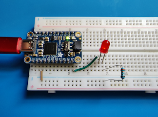
下面是让 LED 闪烁教程的硬件实现,该教程使用 FTDI FT232H 适配器来控制 LED:
在上图中,LED 线路与原始教程非常相似。 唯一的区别是 LED 连接到 FT232H 适配器上的引脚 D7,而不是 Raspberry Pi 上的引脚 18。
本教程的代码也与原始教程相似:
using System.Device.Gpio;
using Iot.Device.Ft232H;
using Iot.Device.FtCommon;

Console.WriteLine("Blinking LED. Press Ctrl+C to end.");

Ft232HDevice ft232h = new Ft232HDevice(FtCommon.GetDevices()[0]);
GpioController controller = ft232h.CreateGpioController();

int pin = Ft232HDevice.GetPinNumberFromString("D7");
controller.OpenPin(pin, PinMode.Output);
bool ledOn = true;
while (true)
{
    controller.Write(pin, ledOn ? PinValue.High : PinValue.Low);
    Thread.Sleep(1000);
    ledOn = !ledOn;
}
在上述代码中:
- 通过将
FtCommon.GetDevices()返回的第一个设备 ID 传递给构造函数来创建Ft232HDevice实例。 - 通过对
Ft232HDevice实例调用CreateGpioController()来创建名为“控制器”的GpioController实例。 此GpioController实例与原始教程中的GpioController实例执行相同函数。 - 通过对
Ft232HDevice实例调用GetPinNumberFromString()并传入字母数字引脚名称 D7 来检索引脚的整数值。 - 代码的其余部分与原始教程相同。
使用 I2C 设备
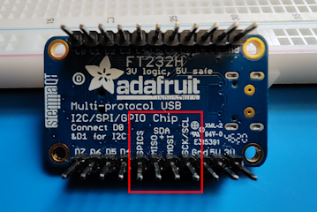
对于 I2C 通信,FT232H 适配器上的 D0 和 D1 引脚分别用于 SDL 和 SCA 线路。 FT232H 适配器上的 I2C 选择器开关必须设置为“开”。
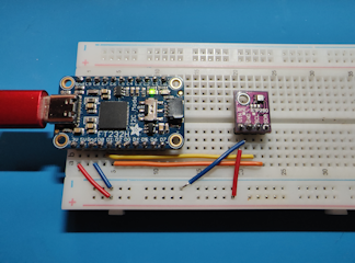
下面是从传感器读取环境条件教程的硬件实现,该教程使用 FTDI FT232H 适配器从 BME280 传感器读取温度、湿度和气压:
在上图中:
- FT232H 适配器上的 D0 和 D1 引脚分别连接到 BME280 分线板上的 SDL 和 SCA 引脚。
- BME280 分线板上的 I2C 选择器开关设置为“开”。
using System.Device.I2c;
using Iot.Device.Bmxx80;
using Iot.Device.Bmxx80.PowerMode;
using Iot.Device.Ft232H;
using Iot.Device.FtCommon;

Ft232HDevice ft232h = new Ft232HDevice(FtCommon.GetDevices()[0]);
I2cConnectionSettings i2cSettings = new I2cConnectionSettings(0, Bme280.SecondaryI2cAddress);

using I2cDevice i2cDevice = ft232h.CreateI2cDevice(i2cSettings);
using Bme280 bme280 = new Bme280(i2cDevice);

int measurementTime = bme280.GetMeasurementDuration();

while (true)
{
    Console.Clear();

    bme280.SetPowerMode(Bmx280PowerMode.Forced);
    Thread.Sleep(measurementTime);

    bme280.TryReadTemperature(out var tempValue);
    bme280.TryReadPressure(out var preValue);
    bme280.TryReadHumidity(out var humValue);
    bme280.TryReadAltitude(out var altValue);

    Console.WriteLine($"Temperature: {tempValue.DegreesCelsius:0.#}\u00B0C");
    Console.WriteLine($"Pressure: {preValue.Hectopascals:#.##} hPa");
    Console.WriteLine($"Relative humidity: {humValue.Percent:#.##}%");
    Console.WriteLine($"Estimated altitude: {altValue.Meters:#} m");

    Thread.Sleep(1000);
}
在上述代码中:
- 通过将
FtCommon.GetDevices()返回的第一个设备 ID 传递给构造函数来创建Ft232HDevice实例。 - 通过对
Ft232HDevice实例调用CreateI2cDevice()来创建I2cDevice实例。 此I2cDevice实例与原始教程中的I2cDevice实例执行相同函数。 - 代码的其余部分与原始教程相同。
使用 SPI 设备
对于 SPI 通信,FT232H 适配器上的 D0、D1、D2 和 D3 引脚分别用于 SCK、MOSI、MISO 和 CS 线路。 FT232H 适配器上的 I2C 选择器开关必须设置为“关”。
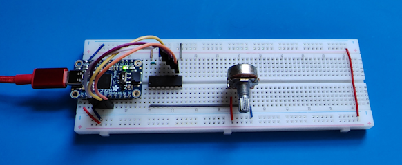
下面是从模拟转数字转换器读取值教程的硬件实现,该教程使用 FTDI FT232H 适配器从 MCP3008 ADC 读取值:
在上图中:
- FT232H 适配器上的 D0、D1、D2 和 D3 引脚分别连接到 MCP3008 上的 CLK、DIN、DOUT 和 CS/SHDN 引脚。
- MCP3008 分线板上的 I2C 选择器开关设置为“关”。
using System.Device.Gpio;
using System.Device.Spi;
using Iot.Device.Adc;
using Iot.Device.Ft232H;
using Iot.Device.FtCommon;

var devices = FtCommon.GetDevices();
var ft232h = new Ft232HDevice(devices[0]);
var hardwareSpiSettings = new SpiConnectionSettings(0, 3) { ClockFrequency = 1_000_000, DataBitLength = 8, ChipSelectLineActiveState = PinValue.Low };
using SpiDevice spi = ft232h.CreateSpiDevice(hardwareSpiSettings);
using var mcp = new Mcp3008(spi);
while (true)
{
    Console.Clear();
    double value = mcp.Read(0);
    Console.WriteLine($"{value}");
    Console.WriteLine($"{Math.Round(value/10.23, 1)}%");
    Thread.Sleep(500);
}
在上述代码中:
- 通过将
FtCommon.GetDevices()返回的第一个设备 ID 传递给构造函数来创建Ft232HDevice实例。 - 通过对
Ft232HDevice实例调用CreateSpiDevice()来创建SpiDevice实例。 此SpiDevice实例与原始教程中的SpiDevice实例执行相同函数。 - 代码的其余部分与原始教程相同。
获取代码
GitHub 上提供了此教程的代码。


