Store organizational hierarchy data
The environmental, social, and governance (ESG) data model schema comes with a robust set of tables to store the details of the entities that play a key role in your organization’s ESG journey. It's important to capture the metadata and the relationships between each of these entities. This effort ensures accuracy while adding filters, performing rollups, drilldowns, aggregations, calculations, and reporting ESG metrics.
Here are some of the key organization tables in the ESG data model schema.
| Table name | Description |
|---|---|
| Legal Entity | A Legal Entity is a nonhuman entity that the law treats for some purposes as if it were a person, such as an incorporated organization. The law allows them to act as persons for certain limited purposes, most commonly lawsuits, property ownership, and contracts. A Legal Entity has a "legal personality" that refers to the ability of an organization to enter into legal transactions such as holding property or entering into debt. |
| Facility | The base location at which you measure your carbon emission, water consumption, or waste generated data. Can be a group of multiple buildings, equipment, or supporting assets. Typically the lowest level at which you can report your ESG metrics. |
| Party Organization | The structural or virtual divisions created within a company or organization. It's a business unit, organizational unit, or department at which data can be aggregated, rolled-up, or reported at each level. |
| Party | Party is a concept that lets individuals, organizations, legal entities, social organizations, and business units to be related or defined with the context of roles, events, and relationships. It lets you "anchor" disparate instances or implementations of each of these options to a common or singular instance of that individual, organization, legal entity, social organization, or business unit. |
| Related Party | Stores the relationship between two parties during the associated period. |
The organizational hierarchy of your organization can fall into one of these two types:
- Simple tree structure (each entity has only a single parent)
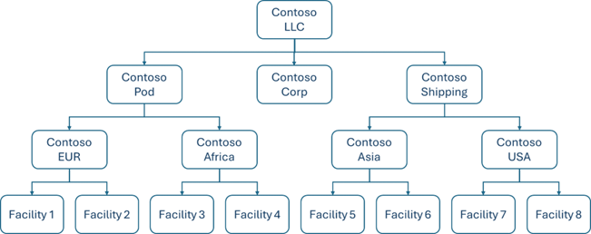
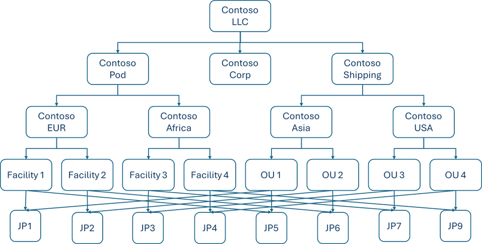
- Graph structure (an entity can have more than one parent)
Simple tree organization structure
Create Party records. Create a Party record for each entity in your organizational hierarchy. Specify the Party type as one among Facility, Organizational unit, or Legal Entity. If the entity doesn't fall into any of these Party types, then you can add your own Party type as a reference value using the steps mentioned in Create, configure, and harmonize reference values.
Note
Adding custom Party types may require customizations to the pre-packaged Sustainability data solutions in Microsoft Fabric notebooks. Unless you capture your ESG measurement data at a lower granularity than a Facility, it is recommended that you use Facility as the Party type for all the entities at the lowest level of your organizational structure.
Store location data for each Party. For each entity in your organizational hierarchy, create a record in the Location table with its location details such as address, state, city, country ID, zip code, etc. Based on the Party type of the Party record, create a subsequent record in the Legal Entity, Facility, or Party Organization (Party type = Organizational unit) tables linking the Party ID and the Location ID values.
If the Party type doesn't belong to any of these options, create a record in the Party Location table to link the Party ID and the Location ID values.
Store the relationships between parties. To store the relationships between each entity, create a record for each relationship in the Related Party table. The Related Party ID field stores the Party ID of the parent, and the Party ID field stores the Party ID of the child. You can specify the party relationship type as a parent-child relationship. You can use the party relationship period start and end timestamps to denote the validity of the relationship.
Note
You can also define your own party relationship types by adding them as reference values using the steps mentioned in Create, configure, and harmonize reference values.
Example:

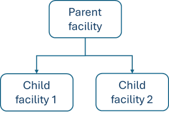
The relationship between the parent facility, child facility 1, and child facility 2 can be stored as indicated in these tables.
Table name: Party
| Attribute | Value | Value | Value |
|---|---|---|---|
| Party ID | 1 | 2 | 3 |
| Party Name | Parent party | Child party 1 | Child party 2 |
| Party Type ID (FK) | 0 (Facility) | 0 (Facility) | 0 (Facility) |
Table name: Location
| Attribute | Value | Value | Value |
|---|---|---|---|
| Location ID | 1 | 2 | 3 |
| Location Name | Parent location | Child 1 location | Child 2 location |
| Country ID (FK) | 840 | 250 | 36 |
Table name: Facility
| Attribute | Value | Value | Value |
|---|---|---|---|
| Facility ID | 1 | 2 | 2 |
| Facility Name | Parent facility | Child facility 1 | Child facility 2 |
| Party ID (FK) | 1 | 2 | 3 |
| Location ID (FK) | 1 | 2 | 3 |
Table name: Related Party
| Attribute | Value | Value |
|---|---|---|
| Party ID (FK) | 2 | 3 |
| Related Party ID (FK) | 1 | 1 |
| Party Relationship Type ID (FK) | 0 | 0 |
| Party Relationship Period Start Timestamp | 1/1/1900 | 1/1/1900 |
| Party Relationship Period End Timestamp | 1/1/2100 | 1/1/2100 |
Graph organization structure (multiple parent nodes)
Create Party records. Create a Party record for each entity in your organizational hierarchy. Specify the Party type as one among Facility, Organizational unit, or Legal Entity. If the entity doesn't fall into any of these Party types, then you can add your own Party type as a reference value using the steps mentioned in Create, configure, and harmonize reference values.
Note
Adding custom Party types may require customizations to the pre-packaged Sustainability data solutions in Fabric notebooks. Unless you capture your ESG measurement data at a lower granularity than a Facility, it is recommended that you use Facility as the Party type for all the entities at the lowest level of your organizational structure.
Store location data for each Party. For each entity in your organizational hierarchy, create a record in the Location table with its location details such as address, state, city, country ID, zip code, etc. Based on the Party type of the Party record, create a subsequent record in the Legal Entity, Facility, or Party Organization (Party type = Organizational unit) tables linking the Party ID and the Location ID values.
In case the Party type doesn't belong to any of these options, create a record in the Party Location table to link the Party ID and the Location ID values.
Store the relationships between parties (with single parent). To store the relationships between each entity, create a record for each relationship in the Related Party table. The Related Party ID field stores the Party ID of the parent, and the Party ID field stores the Party ID of the child. You can specify the party relationship type as parent-child. You can use the party relationship period start and end timestamps to denote the validity of the relationship.
Store the relationships between parties (with multiple parents).
Create joint party records for each combination. Create a party record with the party type as Facility Organization Unit Joint Party, or create your own party types by adding them as reference values using the steps mentioned in Create, configure, and harmonize reference values. All the measurement data associated with the combination of the parties must be added to the joint party record.
Create records in the related party table. To store the multi-parent relationships, create two records in the Related Party table: one to store the relationship between parent 1 party and the joint party, and another to store the relationship between parent 2 party and the joint party. The parent party ID is stored in the Related Party ID field, and the joint party is stored in the Party ID field in the Related Party table. You can specify the party relationship type as FacilityOrganizationUnitJointPartyRelation. You can use the party relationship period start and end timestamps to denote the validity of the relationship.
Note
You can also define your own party relationship types by adding them as reference values using the steps mentioned in Create, configure, and harmonize reference values.
Example:

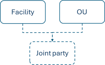
The relationship between the Facility and OU can be stored as follows:
Table name: Party
| Attribute | Value | Value | Value |
|---|---|---|---|
| Party ID | 1 | 2 | 3 |
| Party Name | Facility party | OU party | Joint party |
| Party Type ID (FK) | 0 (Facility) | 2 (OU) | 3 (Facility Organizational Unit Joint Party) |
Table name: Location
| Attribute | Value | Value | Value |
|---|---|---|---|
| Location ID | 1 | 2 | 3 |
| Location Name | Facility location | OU location | Joint party location |
| Country ID (FK) | 840 | 250 | 36 |
Table name: Facility
| Attribute | Value |
|---|---|
| Facility ID | 1 |
| Facility Name | Facility |
| Party ID (FK) | 1 |
| Location ID (FK) | 1 |
Table name: Party Organization
| Attribute | Value |
|---|---|
| Party Organization ID | 1 |
| Party Organization Name | OU |
| Party Organization Party ID (FK) | 2 |
| Location ID (FK) | 2 |
Table name: Party Location
| Attribute | Value |
|---|---|
| Party ID | 3 |
| Location ID | 3 |
| Period Start Timestamp | 1/1/1900 |
| Period End Timestamp | 1/1/2100 |
Table name: Related Party
| Attribute | Value | Value |
|---|---|---|
| Party ID (FK) | 3 | 3 |
| Related Party ID (FK) | 1 | 2 |
| Party Relationship Type ID (FK) | 1 | 1 |
| Party Relationship Period Start Timestamp | 1/1/1900 | 1/1/1900 |
| Party Relationship Period End Timestamp | 1/1/2100 | 1/1/2100 |


