Create maps to transform data in logic app workflows with Visual Studio Code
Applies to: Azure Logic Apps (Standard)
When you exchange messages that use different XML or JSON formats in a logic app workflow, you have to specify how to transform or convert the data from the source format to the target format, for example, between XML documents or between JSON documents. This task is important especially when you have gaps between the data structures in the source and target schemas. A schema describes the data elements, attributes, and data types in an XML or JSON document.
To define transformations between data structures and bridge any gaps, you can create a map (.xslt file) that specifies the relationships between the data elements in the source and target schemas. You can visually create or edit a map by using Visual Studio Code with the Azure Logic Apps (Standard) extension within the context of a Standard logic app project. The Data Mapper tool provides a unified experience for mapping and transformation using drag and drop gestures, prebuilt functions for building expressions, and a way to manually test maps before you use them in your workflows.
After you create your map, you can directly call that map from a workflow in your logic app project or from a Standard logic app workflow in the Azure portal. For this task, you can use the Data Mapper Operations action named Transform using Data Mapper XSLT in your workflow.
This how-to guide shows how to create an empty data map, choose your source and target schemas, create various kinds of mappings between schema elements, save and test your map, and then call the map from a workflow in your logic app project.
Limitations and known issues
Data Mapper currently works only in Visual Studio Code running on Windows operating systems.
Data Mapper is currently available only in Visual Studio Code, not the Azure portal, and only from within Standard logic app projects, not Consumption logic app projects.
Data Mapper currently doesn't support schemas that use the comma-separated values (.csv) file format.
The Code pane in Data Mapper is currently read only.
The layout and item positions in Data Mapper are currently automatic and read only.
The Filter function correctly processes numeric conditions that are enclosed by double quotation marks, for example, ">=10". However, this function currently doesn't consistently behave for string comparisons such as a check on whether an item name is "= 'Pen'".
When you create a mapping between the parent array elements in the source and target schemas, the mapper automatically adds a loop to iterate through the array item elements. However, you must still explicitly create mappings between the source and target array item elements.
To call maps created with Data Mapper, you can only use the Data Mapper Operations action named Transform using Data Mapper XSLT. For maps created by any other tool, use the XML Operations action named Transform XML.
To use the maps that you create with Data Mapper with workflows in the Azure portal, you must add them directly to your Standard logic app resource.
Custom functions currently aren't supported in this release.
Prerequisites
Visual Studio Code and the Azure Logic Apps (Standard) extension to create Standard logic app workflows.
Note
The formerly separate Data Mapper extension is now merged with the Azure Logic Apps (Standard) extension. To avoid conflicts, any existing version of the Data Mapper extension is removed when you install or update the Azure Logic Apps (Standard) extension. After extension install or update, please restart Visual Studio Code.
The source and target schema files that describe the data types to transform. These files can have either the following formats:
- An XML schema definition file with the .xsd file extension
- A JavaScript Object Notation file with the .json file extension
A Standard logic app project that includes a stateful or stateless workflow with a trigger at minimum. If you don't have a project, follow these steps in Visual Studio Code:
Connect to your Azure account, if you haven't already.
Create a local folder, a local Standard logic app project, and a stateful or stateless workflow. During workflow creation, select Open in current window.
Sample input data if you want to test the map and check that the transformation works as you expect.
To use the Run XSLT function, your XSLT snippets must exist in files that use either the .xml or .xslt file name extension. You must put your XSLT snippets in the InlineXslt folder in your local project folder structure: Artifacts > DataMapper > Extensions > InlineXslt. If this folder structure doesn't exist, create the missing folders.
Create a data map
In Visual Studio Code, open the folder for your Standard logic app project.
On the Visual Studio Code left menu, select the Azure icon.
In the Azure window, under Data Mapper, select Create data map.
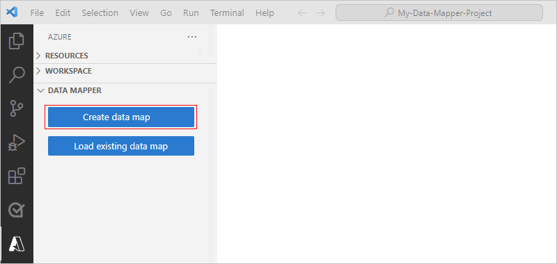
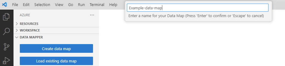
On the Visual Studio Code title bar, a prompt box opens so you can provide a name for your map.
In the prompt box, enter a data map name.
For this guide, these steps use the name Example-data-map.
The Data Mapper creates and opens a blank data map.
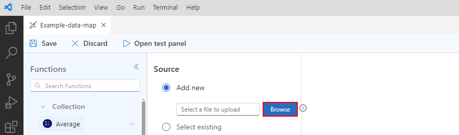
Choose your source and target schemas by following these steps:
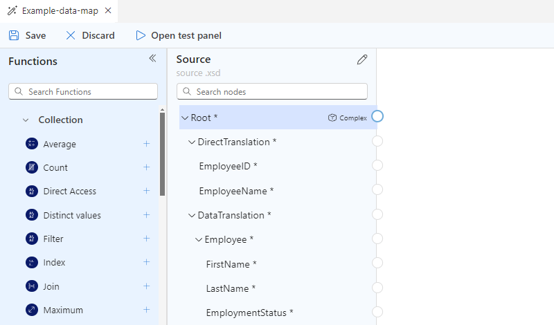
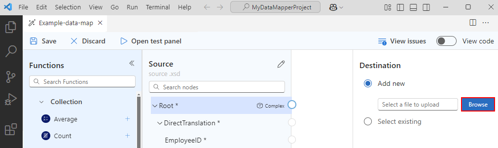
In the Source pane, select Add new > Browse to find and upload your source schema.
After you add your source schema, the Source pane populates with the XML element "nodes" for the data types in the source schema, for example:
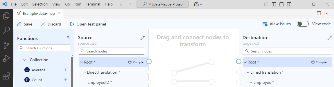
In the Destination pane, select Add new > Browse to find and upload your target schema.
After you add your target schema, the Destination pane populates with the XML element "nodes" for the data types in the target schema, for example:
Tip
If you experience problems loading your schemas, you can locally add your source and target schema files to your logic app project's Artifacts/Schemas folder. In this scenario, to specify your source and target schema in Data Mapper, on the Source and Destination panes, open the Select existing list, rather than use Add new, and select your schema.
Schema data types
The following table describes the possible data types that might appear in a schema:
| Symbol | Type | More info |
|---|---|---|
| Complex (Array) | Contains items or repeating item nodes. An array element also displays the following connection point:  |
|
| Bool | True or false only | |
| Complex | An XML object with children properties, similar to the Object JSON type | |
| DateTime | ||
| Decimal | ||
| Integer | Whole numbers only | |
| String |
Create a direct mapping between elements
To specify a straightforward transformation between elements that have the same type in the source and target schemas, follow these steps:
To view what happens in code while you create the mapping, in the mapper's upper right corner, select View code.
On the mapper surface, in the Source pane, find the source element that you want to map.
By default, parent elements are automatically expanded to show their children.
This example starts mapping from the source element, but you can choose to start mapping from the target element.
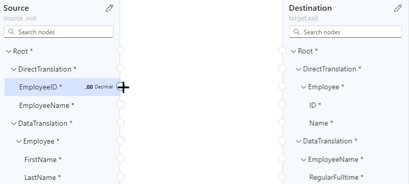
Move your mouse pointer over the circle next to the source element name until the pointer changes to a plus sign (+).
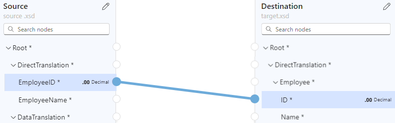
This example creates a mapping starting from the Employee ID source element.
Drag and draw a line so that the source element connects to the circle for the target element in the Destination pane.
This example completes the mapping with the ID target element, which has the same data type as the source element.
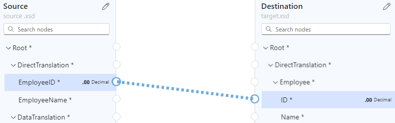
You've now created a direct mapping between both elements that have the same data types.
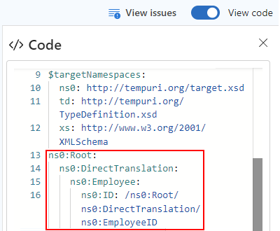
The Code pane shows the mapping relationship that you created:
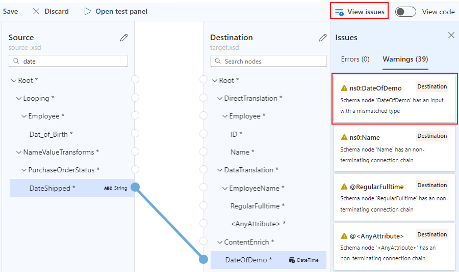
Tip
To check whether your mappings have any problems, select View issues. For example, a warning appears in the Issues list on the Warnings tab if you create a mapping between elements that have mismatched data types:
Create a complex mapping between elements
To specify a more complicated transformation between elements in the source and target schemas, for example, elements that you want to combine or have different data types, you can use one or more functions that perform the transformation that you want in your mapping.
On the mapper surface, the function label is color-coded based on the function group. Next to the function name, the function's symbol appears, for example:

The following table lists the function groups and some example functions that you can use. For the complete list, see the Functions list in Data Mapper.
| Group | Example functions |
|---|---|
| Collection | Average, Count, Direct Access, Distinct values, Filter, Index, Join, Maximum, Minimum, Reverse, Sort, Subsequence, Sum |
| Conversion | To Date, To Integer, To Number, To String |
| Date and time | Add Days, Current Date, Current Time, Equals Date |
| Logical comparison | Equal, Exists, Greater, Greater or equal, If, If Else, Is Nil, Is Null, Is Number, Is String, Less, Less or Equal, Logical AND, Logical NOT, Logical OR, Not Equal |
| Math | Absolute, Add, Arctangent, Ceiling, Cosine, Divide, Exponential, Exponential (base 10), Floor, Integer Divide, Log, Log (base 10), Module, Multiply, Power, Round, Sine, Square Root, Subtract, Tangent |
| String | Codepoints to String, Concat, Contains, Ends with, Length, Lowercase, Name, Regular Expression Matches, Regular Expression Replace, Replace, Starts with, String to Codepoints, Substring, Substring after, Substring before, Trim, Trim Left, Trim Right, Uppercase |
| Utility | Copy, Error, Execute XPath, Format DateTime, Format Number, Run XSLT |
Add a function without a mapping
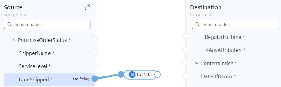
The example in this section transforms data in the source element from String to DateTime, which is the target element type. The example starts without first creating a mapping and uses the To Date function, which accepts a single input.
To view what happens in code while you create the mapping, in the mapper's upper right corner, select View code.
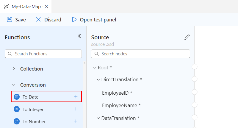
In the Functions list, find and select the function that you want to use, which adds the function to the mapper surface. If the Functions list is collapsed, in the mapper's upper left corner, select the function icon (
 ).
).This example selects the To Date function, which is in the Conversion function group.
Note
If no mapping exists on the map or if a mapping is selected when you add a function to the map, the function appears but isn't connected to any elements or other functions, for example:

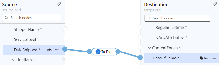
Connect the function to the source and target elements.
Drag and draw a line between the source element and the circle on the function's left edge. You can start from either the source element or the function.
Drag and draw a line between the function's right edge and the target element. You can start from either from the target element or the function.
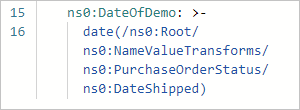
The Code pane shows the mapping relationship that you created:
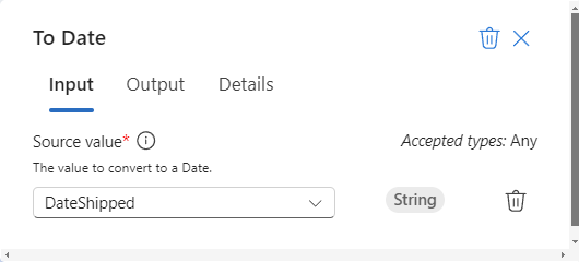
On the mapper surface, select the function shape to view the function details.
On the Input tab, confirm or edit the input to use.
Some scenarios require defining a transformation beyond the immediate pair of source and target elements. For example, to define a transformation between a pair of arrays and their items, you need to create a loop between the arrays. Or, to perform a task when an element's value meets a condition, you need to add a condition between elements.
Add a function that uses multiple inputs
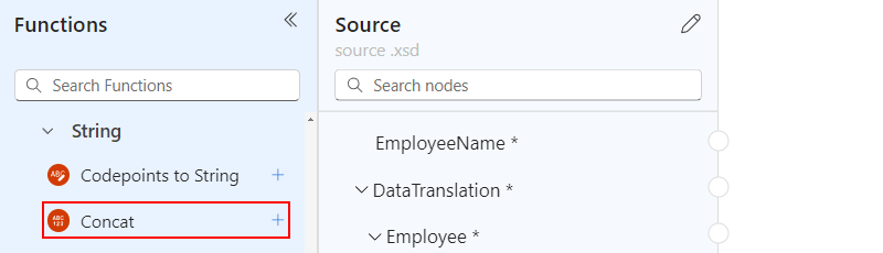
The example in this section concatenates multiple source elements as inputs and maps a single output to the target element. The example uses the Concat function, which accepts multiple inputs.
To view what happens in code while you create the mapping, in the mapper's upper right corner, select View code.
In the Functions list, find and select the function that you want to use, which adds the function to the mapper surface.
If the Functions list is collapsed, in the mapper's upper left corner, select the function icon (
).This example selects the Concat function, which is in the String function group.
Note
If no mapping exists on the map or if a mapping is selected when you add a function to the map, the function appears but isn't connected to any elements or other functions, for example:

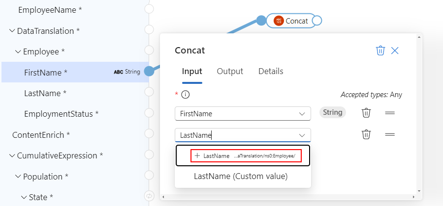
On the mapper surface, select the function shape to view the function details.
On the Input tab, select the source schema elements to use as the inputs.
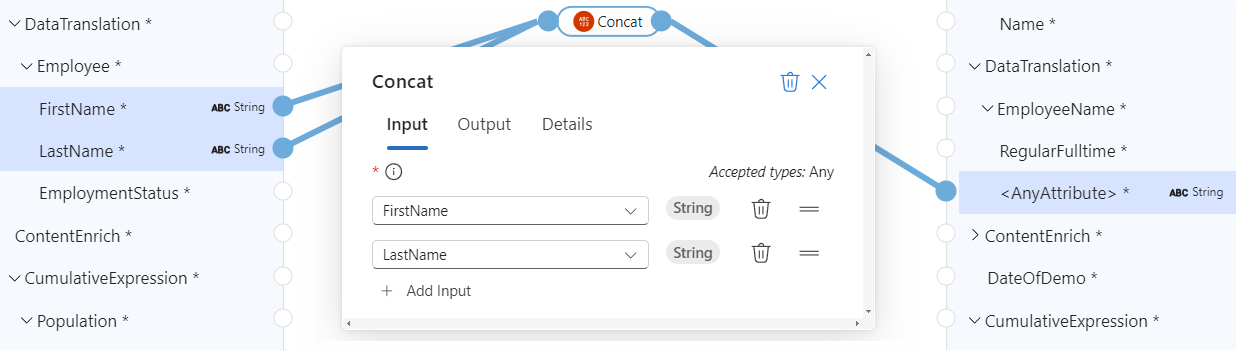
This example selects the FirstName and LastName source schema elements as the function inputs. The mapper automatically adds the respective mappings between the source elements and the function.
To complete the mapping, drag and draw a line between the function's right edge and the target element. You can start from either the target element or the function.
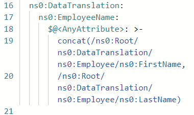
The Code pane shows the mapping relationships that you created:
Iterate through arrays
If your source and target schemas contain arrays, you can create a loop to iterate through the arrays' items. The example in this section creates a loop through an Employee source array and a Person target array along with mappings between the arrays' items.
To view what happens in code while you create the mapping, in the mapper's upper right corner, select View code.
On the mapper surface, in the Source and Destination panes, find the arrays that you want to map.
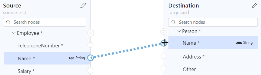
Drag and draw a line between the pair of array items. You can start from either the Source pane or the Destination pane.
The following example starts from the Source pane and maps the Name items in the Employee source array and the Person target array:
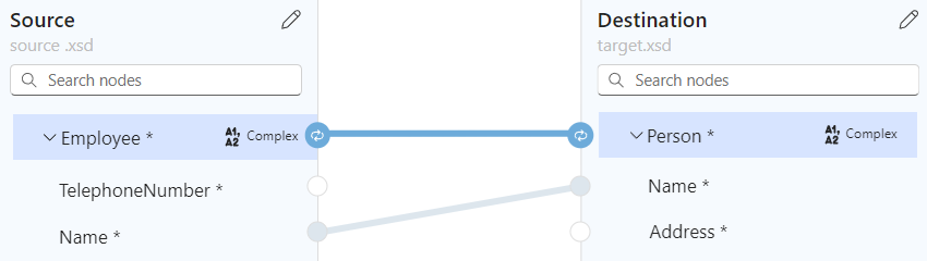
After you finish mapping the first pair of array items, the mapper automatically adds a loop between the source and target array parent elements, which have the following connection point type:

The following example highlights the automatically added loop between the source Employee and target Person parent arrays:
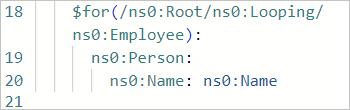
The Code pane shows the mapping and loop that you created:
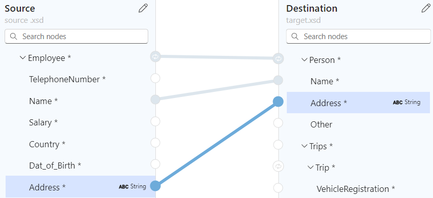
Continue mapping the other array elements, for example:
Evaluate a condition to perform a task
Suppose you want to add a mapping that evaluates a condition and performs a task when the condition is met. For this scenario, you can use multiple functions.
In the following example, when the purchase quantity exceeds 20 items, the mapping calculates a discount to apply by using the following functions:
| Function group | Function | Purpose in this example |
|---|---|---|
| Comparison | Greater | Check whether purchase quantity is more than 20. |
| Comparison | If | Check whether the Greater function returns true. |
| Math | Multiply | If condition is true, multiply the item price by 10% to calculate the discount. |
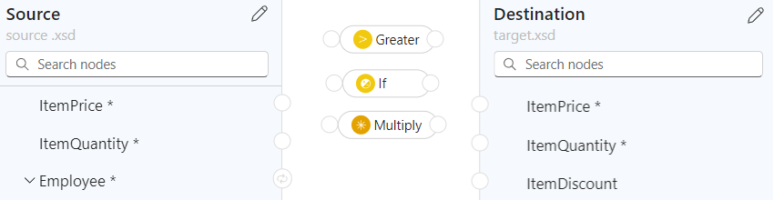
In the Source and Destination panes, find the elements to map in your scenario.
This example uses the following elements:
Source pane: ItemPrice and ItemQuantity
Destination pane: ItemPrice, ItemQuantity, and ItemDiscount

In the Functions list, find and select the functions that you want to use, which adds the functions to the mapper surface.
If the Functions list is collapsed, in the mapper's upper left corner, select the function icon (
).If necessary, move the function shapes on the mapper surface to make them easier to select.
This example adds the following functions to the mapper surface: Greater, If, and Multiply
To view what happens in code while you create the mappings, in the mapper's upper right corner, select View code.
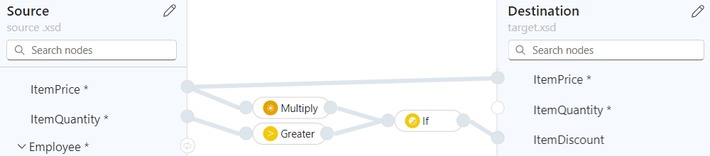
Connect the source elements, functions, and target elements in the specific order as your scenario requires.
This example connects the following items in the specified order to correctly create the mappings:
Start End ItemPrice source element ItemPrice target element ItemQuantity source element Greater function's input on the shape's left edge. This input provides the data for the Value 1 field in the function details. Greater function's output on the shape's right edge If function's input on the shape's left edge. This input provides the data for the Condition field in the function details. ItemPrice source element Multiply function's input on the shape's left edge. This input provides the data for the Multiplicand field in the function details. Multiply function's output on the shape's right edge. If function's input on the shape's left edge. This input provides the data for the Value field in the function details. If function's output on the shape's right edge. ItemDiscount target element The following example shows the mappings at this point in time:
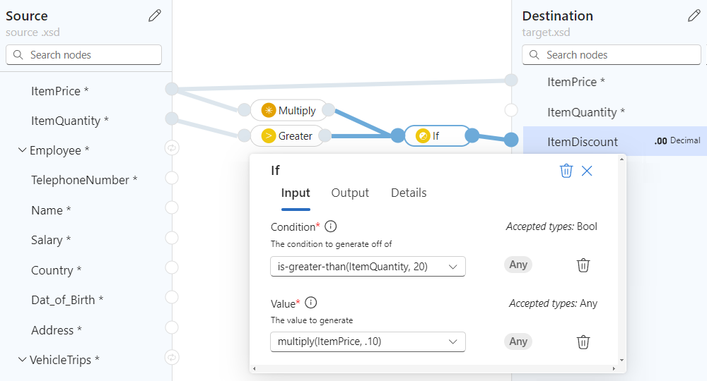
In the following function details, on the Input tab, confirm or provide the following values:
Function Input field and value Greater - Value 1: ItemQuantity source element
- Value 2: 20 as a custom valueMultiply - Multiplicand 1: ItemPrice source element
- Multiplicand 2: .10 as a custom valueIf - Condition: is-greater-than(ItemQuantity, 20)
- Value: multiply(ItemPrice, .10)The following map shows the finished example:
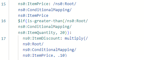
The Code pane shows the mapping that you created:
Save your map
When you're done, on the map toolbar, select Save.
Visual Studio Code saves your map as the following artifacts:
- A <your-map-name>.lml file in the Artifacts > MapDefinitions project folder
- An <your-map-name>.xslt file in the Artifacts > Maps project folder
Test your map
To confirm that the transformation works as you expect, you'll need sample input data.
Before you test your map, save the map to generate a current <your-map-name>.xslt file.
On your map toolbar, select Open test panel.
On the Test map pane, in the Sample data box, paste your sample input, and select Test.
The Result box shows the test results.
Call your map from a workflow in your project
On the Visual Studio Code Activity bar, select Explorer (files icon) to view your logic app project structure.
Expand the folder that has your workflow name. From the workflow.json file's shortcut menu, select Open Designer.
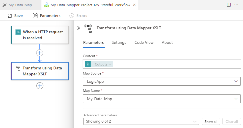
On the workflow designer, follow these general steps to add the Data Mapper Operations built-in action named Transform using Data Mapper XSLT.
On the designer, select the Transform using Data Mapper XSLT action.
On the action information pane that appears, specify the Content value, and leave Map Source set to LogicApp.
Open the Map Name list, and select your map (.xslt file).
To use the same Transform using Data Mapper XSLT action in the Azure portal, you must add the map to the Standard logic app resource.
Related content
- For data transformations using B2B operations in Azure Logic Apps, see Add maps for transformations in workflows with Azure Logic Apps