D2D1_FILL_MODE enumeration (d2d1.h)
Specifies how the intersecting areas of geometries or figures are combined to form the area of the composite geometry.
Syntax
typedef enum D2D1_FILL_MODE {
  D2D1_FILL_MODE_ALTERNATE = 0,
  D2D1_FILL_MODE_WINDING = 1,
  D2D1_FILL_MODE_FORCE_DWORD = 0xffffffff
} ;
Constants
D2D1_FILL_MODE_ALTERNATEValue: 0 Determines whether a point is in the fill region by drawing a ray from that point to infinity in any direction, and then counting the number of path segments within the given shape that the ray crosses. If this number is odd, the point is in the fill region; if even, the point is outside the fill region. |
D2D1_FILL_MODE_WINDINGValue: 1 Determines whether a point is in the fill region of the path by drawing a ray from that point to infinity in any direction, and then examining the places where a segment of the shape crosses the ray. Starting with a count of zero, add one each time a segment crosses the ray from left to right and subtract one each time a path segment crosses the ray from right to left, as long as left and right are seen from the perspective of the ray. After counting the crossings, if the result is zero, then the point is outside the path. Otherwise, it is inside the path. |
D2D1_FILL_MODE_FORCE_DWORDValue: 0xffffffff |
Remarks
Use the D2D1_FILL_MODE enumeration when creating an ID2D1GeometryGroup with the CreateGeometryGroup method, or when modifying the fill mode of an ID2D1SimplifiedGeometrySink with the ID2D1SimplifiedGeometrySink::SetFillMode method.
Direct2D fills the interior of a path by using one of the two fill modes specified by this enumeration: D2D1_FILL_MODE_ALTERNATE (alternate) or D2D1_FILL_MODE_WINDING (winding). Because the modes determine how to fill the interior of a closed shape, all shapes are treated as closed when they are filled. If there is a gap in a segment in a shape, draw an imaginary line to close it.
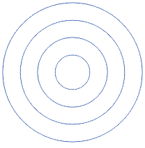
To see the difference between the winding and alternate fill modes, assume that you have four circles with the same center and a different radius, as shown in the following illustration. The first one has the radius of 25, the second 50, the third 75, and the fourth 100.
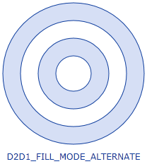
 The following illustration shows the shape filled by using the alternate fill mode. Notice that the center and third ring are not filled. This is because a ray drawn from any point in either of those two rings passes through an even number of segments.
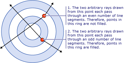
 The following illustration explains this process.
 The following illustration shows how the same shape is filled when the winding fill mode is specified.
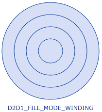 Notice that all the rings are filled. This is because all the segments run in the same direction, so a ray drawn from any point will cross one or more segments, and the sum of the crossings will not equal zero.
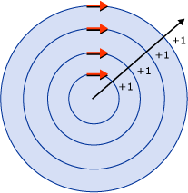
The following illustration explains this process. The red arrows represent the direction in which the segments are drawn and the black arrow represents an arbitrary ray that runs from a point in the innermost ring. Starting with a value of zero, for each segment that the ray crosses, a value of one is added for every clockwise intersection. All points lie in the fill region in this illustration, because the count does not equal zero.
Examples
The following code example creates the geometry groups used the preceding illustrations. The code first declares an array of geometry objects. These objects are four concentric circles that have the following radii: 25, 50, 75, and 100. Then call the CreateGeometryGroup on the ID2D1Factory object, passing in D2D1_FILL_MODE_ALTERNATE, an array of geometry objects to add to the geometry group, and the number of elements in this array.
HRESULT DemoApp::CreateGeometryResources()
{
    HRESULT hr;

    const D2D1_ELLIPSE ellipse1 = D2D1::Ellipse(
        D2D1::Point2F(105.0f, 105.0f),
        25.0f,
        25.0f
        );

    hr = m_pD2DFactory->CreateEllipseGeometry(
        ellipse1,
        &m_pEllipseGeometry1
        );

    if (SUCCEEDED(hr))
    {
        const D2D1_ELLIPSE ellipse2 = D2D1::Ellipse(
            D2D1::Point2F(105.0f, 105.0f),
            50.0f,
            50.0f
            );

        hr = m_pD2DFactory->CreateEllipseGeometry(
            ellipse2,
            &m_pEllipseGeometry2
            );
    }

    if (SUCCEEDED(hr))
    {

        const D2D1_ELLIPSE ellipse3 = D2D1::Ellipse(
            D2D1::Point2F(105.0f, 105.0f),
            75.0f,
            75.0f
            );

        hr = m_pD2DFactory->CreateEllipseGeometry(
            ellipse3,
            &m_pEllipseGeometry3
            );
    }

    if (SUCCEEDED(hr))
    {
        const D2D1_ELLIPSE ellipse4 = D2D1::Ellipse(
            D2D1::Point2F(105.0f, 105.0f),
            100.0f,
            100.0f
            );

        hr = m_pD2DFactory->CreateEllipseGeometry(
            ellipse4,
            &m_pEllipseGeometry4
            );
    }

    if (SUCCEEDED(hr))
    {
        ID2D1Geometry *ppGeometries[] =
        {
            m_pEllipseGeometry1,
            m_pEllipseGeometry2,
            m_pEllipseGeometry3,
            m_pEllipseGeometry4
        };

        hr = m_pD2DFactory->CreateGeometryGroup(
            D2D1_FILL_MODE_ALTERNATE,
            ppGeometries,
            ARRAYSIZE(ppGeometries),
            &m_pGeoGroup_AlternateFill
            );

        if (SUCCEEDED(hr))
        {
            hr = m_pD2DFactory->CreateGeometryGroup(
                D2D1_FILL_MODE_WINDING,
                ppGeometries,
                ARRAYSIZE(ppGeometries),
                &m_pGeoGroup_WindingFill
                );
        }

    }
    return hr;
}
Requirements
| Requirement | Value |
|---|---|
| Minimum supported client | Windows 7, Windows Vista with SP2 and Platform Update for Windows Vista [desktop apps | UWP apps] |
| Minimum supported server | Windows Server 2008 R2, Windows Server 2008 with SP2 and Platform Update for Windows Server 2008 [desktop apps | UWP apps] |
| Header | d2d1.h |