Jak tworzyć połączone geometrie
W tym przykładzie pokazano, jak połączyć geometrie. Aby połączyć dwie geometrie, użyj CombinedGeometry obiektu. Ustaw jego Geometry1 właściwości i Geometry2 z dwiema geometriami, aby połączyć, i ustawić GeometryCombineMode właściwość, która określa, jak geometrie będą łączone razem, na Union, , IntersectExcludelub Xor.
Aby utworzyć geometrię złożoną na podstawie co najmniej dwóch geometrii, użyj elementu GeometryGroup.
Przykład
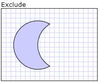
W poniższym przykładzie CombinedGeometry element jest zdefiniowany z trybem Excludełączenia geometrii . Oba Geometry1 i Geometry2 są zdefiniowane jako okręgi tego samego promienia, ale z centrami przesuniętymi o 50.
<Path Stroke="Black" StrokeThickness="1" Fill="#CCCCFF">
  <Path.Data>

    <!-- Combines two geometries using the exclude combine mode. -->
    <CombinedGeometry GeometryCombineMode="Exclude">
      <CombinedGeometry.Geometry1>
        <EllipseGeometry RadiusX="50" RadiusY="50" Center="75,75" />
      </CombinedGeometry.Geometry1>
      <CombinedGeometry.Geometry2>
        <EllipseGeometry RadiusX="50" RadiusY="50" Center="125,75" />
      </CombinedGeometry.Geometry2>
    </CombinedGeometry>
  </Path.Data>
</Path>

Wykluczanie połączonej geometrii
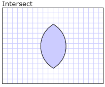
W poniższym znaczniku CombinedGeometry element jest definiowany z trybem Intersectłączenia . Oba Geometry1 i Geometry2 są zdefiniowane jako okręgi tego samego promienia, ale z centrami przesuniętymi o 50.
<Path Stroke="Black" StrokeThickness="1" Fill="#CCCCFF">
  <Path.Data>

    <!-- Combines two geometries using the intersect combine mode. -->
    <CombinedGeometry GeometryCombineMode="Intersect">
      <CombinedGeometry.Geometry1>
        <EllipseGeometry RadiusX="50" RadiusY="50" Center="75,75" />
      </CombinedGeometry.Geometry1>
      <CombinedGeometry.Geometry2>
        <EllipseGeometry RadiusX="50" RadiusY="50" Center="125,75" />
      </CombinedGeometry.Geometry2>
    </CombinedGeometry>
  </Path.Data>
</Path>

Przecięcie połączonej geometrii
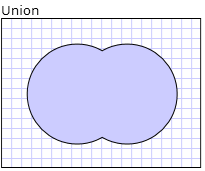
W poniższym znaczniku CombinedGeometry element jest definiowany z trybem Unionłączenia . Oba Geometry1 i Geometry2 są zdefiniowane jako okręgi tego samego promienia, ale z centrami przesuniętymi o 50.
<Path Stroke="Black" StrokeThickness="1" Fill="#CCCCFF">
  <Path.Data>

    <!-- Combines two geometries using the union combine mode. -->
    <CombinedGeometry GeometryCombineMode="Union">
      <CombinedGeometry.Geometry1>
        <EllipseGeometry RadiusX="50" RadiusY="50" Center="75,75" />
      </CombinedGeometry.Geometry1>
      <CombinedGeometry.Geometry2>
        <EllipseGeometry RadiusX="50" RadiusY="50" Center="125,75" />
      </CombinedGeometry.Geometry2>
    </CombinedGeometry>
  </Path.Data>
</Path>

Połączony związek geometrii
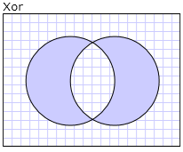
W poniższym znaczniku CombinedGeometry element jest definiowany z trybem Xorłączenia . Oba Geometry1 i Geometry2 są zdefiniowane jako okręgi tego samego promienia, ale z centrami przesuniętymi o 50.
<Path Stroke="Black" StrokeThickness="1" Fill="#CCCCFF">
  <Path.Data>

    <!-- Combines two geometries using the XOR combine mode. -->
    <CombinedGeometry GeometryCombineMode="Xor">
      <CombinedGeometry.Geometry1>
        <EllipseGeometry RadiusX="50" RadiusY="50" Center="75,75" />
      </CombinedGeometry.Geometry1>
      <CombinedGeometry.Geometry2>
        <EllipseGeometry RadiusX="50" RadiusY="50" Center="125,75" />
      </CombinedGeometry.Geometry2>
    </CombinedGeometry>
  </Path.Data>
</Path>

Połączona geometria Xor
.NET Desktop feedback
