Sequential and Flowchart modeling styles
WF 4 ships with an activity palette that consists of many activities – some of these are control flow activities that represent the different modeling styles developers can use to model their business process. Sequence and Flowchart are a couple of modeling styles we ship in WF 4. In this post, we will present these modeling styles, learn what they are, when to use what, and highlight the main differences between them.
Sequential modeling style
A sequential workflow executes a set of contained activities in sequential order. The Sequence activity in WF 4 allows you to model workflows in the sequential modeling style. A Sequence contains a collection of activities that are scheduled in the order in which they have been added to the collection. Hence, the order of execution of the activities is predictable.
You can add any activity to a Sequence – control flow procedural constructs like ForEach, If, Switch, While, DoWhile; or parallel constructs like Parallel and ParallelForEach to model parallel execution of logic; or any other activity we provide in the WF 4 activity palette (or your own custom activity or a third party activity).
The next figure shows a Vacation Approval workflow modeled as a sequential workflow using the Sequence activity and other activities. In this workflow, we first check if the employee has enough available days, wait for his manager approval, and finally update his vacation information in the company’s HR database. The activity highlighted in the orange box (Get Manager Approval) is actually a While activity (collapsed in the main Sequence) that executes another Sequence of activities (AskForApproval) while the approvedByManager variable value is False.
Workflows modeled using the sequential modeling style are easy to understand and author. They can be used to model simple to moderately complex processes. Since procedural activities have strong parity with procedural statements in imperative programming languages, you can use this type of workflows to model almost any type of process. Sequential workflows are also a good fit to model simple processes with no human interactions (e.g. services).
As the complexity of the process increases, the workflow will become more complex. In comparison to code, with workflows, you will get the benefit of visually looking at your process and visual debugging, however, you may want to factor out the logic into re-usable custom activities to improve the readability of large workflows.
Sequential Modeling Style and Sequence Activity
Sequence is not a requirement to create workflows that use the sequential modeling style. As we will explain later in this post, any activity in WF 4 can be the root of a workflow. Therefore, we can create a workflow that does not contain a Sequence but still uses the sequential modeling style and procedural activities. In the figure below, we have a workflow that has as a ForEach as root activity that prints all the items in a list of strings with a length higher than 5.
Flowchart
Flowchart is a well known and intuitive paradigm to visually represent business processes. Business Analysts, Architects and Developers use often flowcharts as common language to express process definitions and flow of logic.
Since the release of WF 3, customers have given us feedback about what they like and don’t like. One common point of feedback from customers using WF3 was that “we want the simplicity of Sequence, Parallel, etc. but the flexibility of StateMachine.” When we dug deeper to get at the scenario behind this sentiment, we found that customers have a process (or a portion of a process) that is often quite sequential in nature but which requires “loopbacks” under certain circumstances (for some customers the circumstances are “exceptional” in nature while for other customers they are “expected” but it really doesn’t matter to this discussion). The FlowChart activity is new in WF 4 and it squarely addresses this (rather large) class of scenarios. Flowchart is a very powerful construct since it provides the simplicity of sequence plus the ability of looping back to a previous point of execution, which is quite common in real life business processes to simulate re-try of logic when handling external input.
A Flowchart contains a set of nodes and arcs. The nodes are FlowNodes – which contain activities or special common constructs such as a 2-way decision or a multi-way switch. The arcs describe potential execution paths through the nodes. The WF 4 Flowchart has a single path of execution; that is, it does not support split/join semantics that would enable multiple interleaved paths of execution.
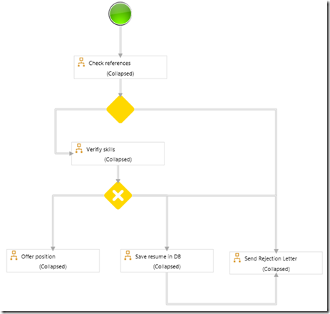
The next figure shows a simplified recruiting process modeled using a Flowchart. In this case after a résumé is received, references are checked. If references are good, the process continues, otherwise the résumé is rejected. The next step verifies that the candidate skills are a good match for the position offered. If the candidate is a good match, then she will be offered a position. If she is not a good match for this position but interesting for future opportunities, the resume is saved in a database and a rejection letter is sent. Finally, if the candidate is not a good match, she is sent a rejection letter.
Flowchart modeling style is great to represent processes that are sequential in nature (with a single path of execution), but have loops to previous states. They use a very well known approach for modeling processes (based on “boxes and arrows”) and allow representing processes in a very visual manner. Control of flow is dominated by the transitions between the nodes and by two first-class branching activities (FlowDecision and FlowSwitch). Flowchart is a good fit to model processes with human interactions (e.g. human workflows).
Using Sequence and Flowchart together
WF 3 had a notion of a root activity. Only root activities could be used as the top level activity in a WF 3 workflow. WF 4 does not have a similar restriction. There is no notion of a root activity any more. Any activity can be the root of a workflow.
Let me explain this in more detail… Activities are a unit of work in WF. Activities can be composed together into larger Activities. When an Activity is used as a top-level entry point, we call it a "Workflow" , just like Main is simply another function that represents a top level entry point to CLR programs. Hence, there is nothing special about using Sequence or Flowchart as the top level activity; and they can be composed at will.
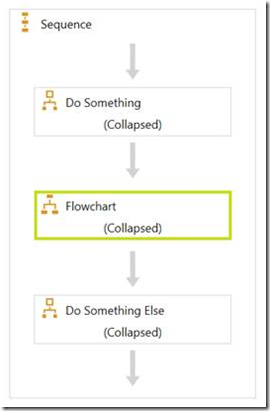
The next figure shows a Flowchart inside a Sequence. The workflow below has three activities: a composite activity that does some work, a Flowchart (highlighted in green) and finally another composite activity that does some more work.
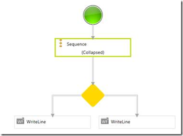
The same can be also done in a Flowchart. The next figure shows a Flowchart that has a Sequence (highlighted in green), a FlowDecision, and then two WriteLine activities for the True and False paths of the decision.
Beyond Sequence and Flowchart
WF 4 simplified activity authoring story makes easier writing your own custom composite activities to model any control of flow approach of your choice. In future posts, we will show how to write your own custom activities and designers.
Conclusion
In this post we have presented the Sequential and Flowchart modeling styles. We learned that Sequence is used for modeling sequential behavior and that Flowchart is used to model processes with a single path of execution and loops to previous states. We also learned that Sequence and Flowchart can be combined and used together as any other existing activity.
The following table shows the main differences between Sequence and Flowchart.
Sequence |
Flowchart |
Order of execution is explicit, close to imperative/code |
Order of execution expressed as a graph with nodes and arcs |
Loopbacks are represented combining control of flow activities (e.g. While + If) |
First class modeling of loopbacks |
Parity with imperative / procedural |
Parity with boxes and arrows diagrams |
Activities are executed in sequential order |
Activities are executed in the order dictated by the arrows between them |
Simple process / no human interaction (e.g. services) |
Complex processes / human interactions (e.g. human workflows / state machine scenarios) |
The flow of the process is not visually obvious |
Control of flow is visual, dominated by Boolean decisions (FlowDecision) or Switch (FlowSwitch) |
Comments
Anonymous
June 15, 2009
PingBack from http://coding.windstyle.cn/2009/06/16/sequential-and-flowchart-modeling-styles/Anonymous
June 19, 2009
Thank you for submitting this cool story - Trackback from DotNetShoutout


