Build a Azure Sphere IoT Car with Remote Control
1. Introduction
In this project, we make use of Avnet Azure Sphere Starter Kit, Arduino Uno and Azure IoT Cloud Services to build an Azure Sphere Remote Sensing Car. The hardware includes Avnet Azure Sphere Starter Kit, Arduino Uno and a car model, while the software includes applications running on Avnet Azure Sphere Starter Kit, Arduino Uno and desktop PC. Azure IoT Cloud Services include Azure IoTHub, Azure Stream Analytics and PowerBI. The video of the project is shown as follows.
View
This project is built based on the work from Peter Fenn and Brian Willess, named "Avnet Azure Sphere Starter-Kit: Advanced Tutorial." Hence, before continue to read the following contents, please make sure that you complete the work that described in the tutorial.
2. System Overview
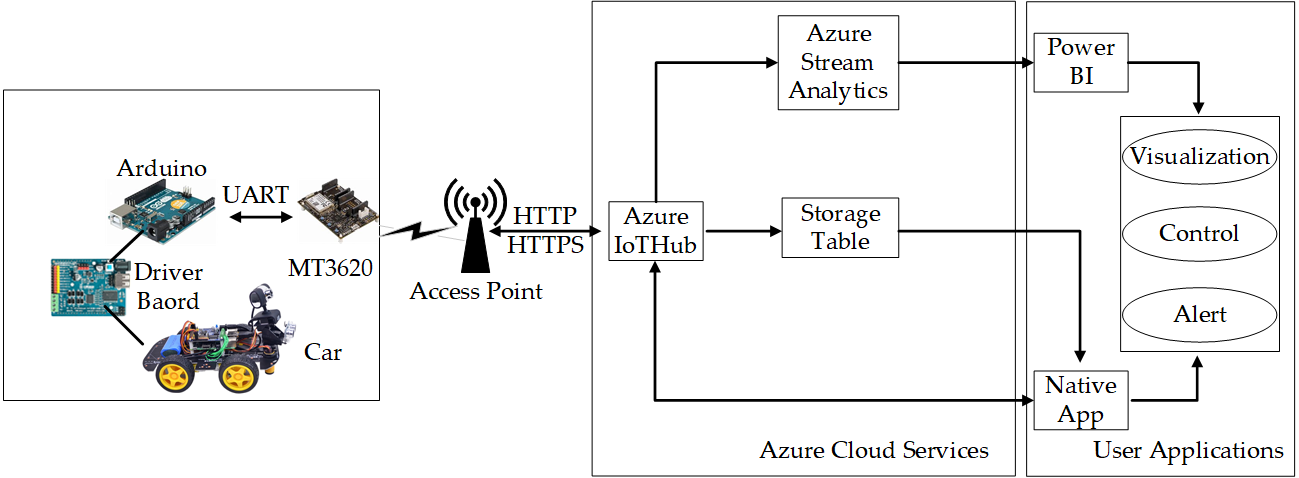
The entire system is shown in Figure 1, which can be divided into three different layers including device layer, cloud layer and application layer. Firstly, a remote sensing car is composed of Avnet Azure Sphere Starter Kit, Arduino Uno and a car model. Secondly, Azure IoT Hub, Azure Stream AnalyticsAzure Storage Table are utilized as the data processing and management unit. Lastly, Power BI and Native App are used as UX solution and business integration.
Figure 1. System overview.
3. Hardware Setup
3.1 Hardware Items Required
- Avnet Azure Sphere MT3620 Starter Kit
- 128x64 Yellow Blue SSD1306 I2C OLED Display [optional]
- Arduino UNO
- A car model
3.2 Connect an OLED Display to Azure Sphere Starter Kit
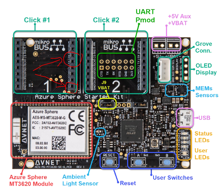
Interface for optional OLED 128x64 display (I2C) is left empty on the board. The pinout of the OLED DISPLAY connector on this Starter Kit is tabled below in Figure 2.
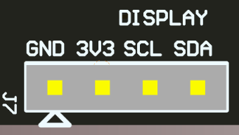
Figure 2. OLED Display Interface
We can solder four 2.54mm Pins on the board to help connecting with OLED display as shown in Figure 3.
Figure 3. Connecting the board with OLED display by four Pins.
3.3 Connect Arduino Uno to Avnet Azure Sphere Kit
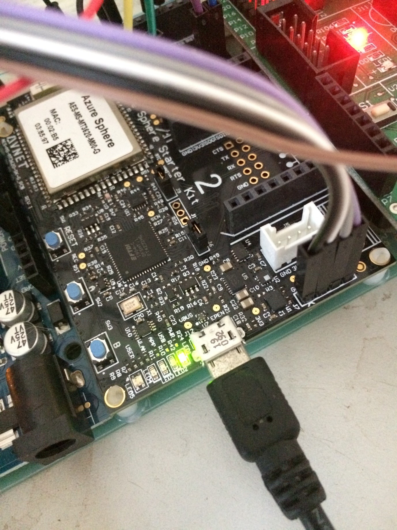
In this project, we use Uart0 of Arduino Uno. So, Pin 0, Pin 1 and GND are used as Rx, Tx and GND for Uart communication. For Avnet Azure Sphere Kit, Uart0 on “Mikrobus Click 1” is used as shown in Figure 4.
Figure 4. Connecting Arduino Uno to Avnet Azure Sphere Kit
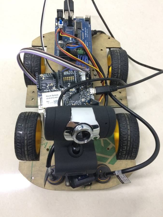
Please make sure that the Rx of Arduino is connect with Tx of Avnet Azure Sphere Kit, and the Tx of Arduino is connect with Rx of Avnet Azure Sphere Kit. The car with Avnet Azure Sphere Kit is shown in Figure 5.
Figure 5. The car with Avnet Azure Sphere Kit
4. Software Design
4.1 Software Required
A Windows 10 PC with Visual Studio 2017 Community or Visual Studio 2019 Community, and Arduino IDE are leveraged to develop applications for MT3260 Starter kits and Arduino Uno respectively. Azure Sphere software development kit (SDK) Version 19.09 (the latest version is 20.01) is also installed as indispensable extensions for Visual Studio Community.
4.2 Software for Arduino Uno
In this project, Arduino Uno is acted as a kind of car controller. In the initialization of the program, the input and output pins are set. And the baud rate of the serial port is configured as 9600. In the main loop, the function of Get_uartdata, UartTimeoutCheck and Cruising_Mod are called in order. Get_uartdata is responsible for uart data receiving, storing and processing. UartTimeoutCheck is used for Uart data receiving time out check. Cruising_Mod is used for mode switching, such as Follow Line Mode, Avoiding Mode and Avoid Wave Mode. Here, we only implement Forward, Back, Stop, Left and Right commands. Please refer to the source code on GitHub for more details: https://github.com/shijiong/AzureSphereRemoteSensingCar/tree/master/ArduinoCar . All commands are encoded in Hex mode, which are shown in the following.
- Forward: 0xFF 0x00 0x01 0x00 0xFF
- Back: 0xFF 0x00 0x02 0x00 0xFF
- Left: 0xFF 0x00 0x03 0x00 0xFF
- Right: 0xFF 0x00 0x04 0x00 0xFF
- Stop: 0xFF 0x00 0x00 0x00 0xFF
- SpeedUp: 0xFF 0x02 0x02 SpeedValue 0xFF
- SlowDown: 0xFF 0x02 0x01 SpeedValue 0xFF
- SlowDown: 0xFF 0x02 0x01 SpeedValue 0xFF
4.3 Software for Avnet Azure Sphere Start Kit
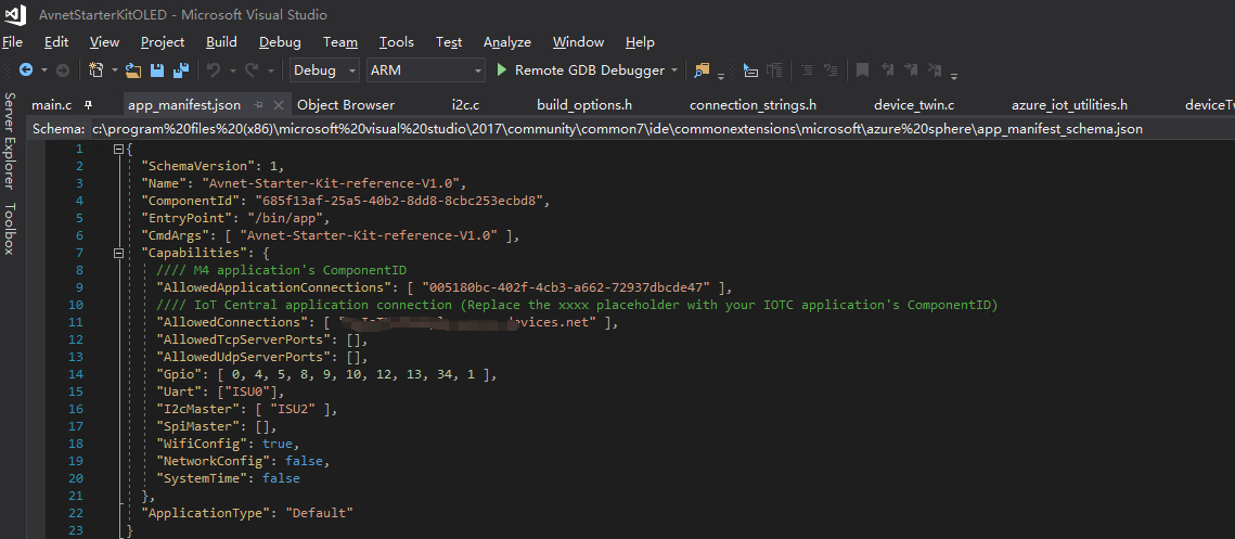
Thanks to Peter Fenn and Brian Willess, the program for Avnet Azure Sphere Start Kit is built on the basis of their work "Avnet Azure Sphere Starter-Kit: Advanced Tutorial." The UART peripheral should be included in the application manifest file, in which all the resources that the application requires are listed. It is noted that the application manifest will be accessed by Azure Sphere runtime to determine which capabilities are allowed to use as soon as the application is sideloaded or deployed to the device. Any attempt to access resources that are not described in the manifest will be denied by the runtime. Hence, UART0 and Allowed Connections to Azure cloud services are added as essential capabilities. It is shown in Figure 6.
Figure 6. The application manifest file for the project of MT3620
It should be noted that the “AllowedConnections” should be changed to your own Azure IoTHub.
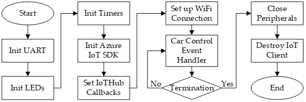
The flowchart of the application that is running in the MT3620 is depicted in Figure 7. In the initialization process, the UART peripheral is configured and opened for communication with Arduino Uno. In the azure_iot_utilities.c, the Cloud-to-Device message is handled by the “receiveMessageCallback” function, in which the global Boolean variables including moveLeft, moveRight, moveForward, moveBack, and moveStop are changed according to the receiving message. In the main loop, the CarControlHandler is called for car controlling according to the values of five global Boolean variables.
Figure 7. The flowchart of the application running on MT3620.
The commands are handled and sent to the Arduino Car by CarControlHandler as follows.
01.//       Car Control EventHandler Shijiong
02./// <summary>
03.///     Handle car control event.
04./// </summary>
05.static void  CarControlHandler()
06.{
07.    uint8_t commandSequence[5];
08.
09.    if (moveLeft)
10.    {
11.        moveLeft = false;
12.        commandSequence[0] = 0xff;
13.        commandSequence[1] = 0x00;
14.        commandSequence[2] = 0x03;
15.        commandSequence[3] = 0x00;
16.        commandSequence[4] = 0xff;
17.        SendUartMessage(uart0Fd, commandSequence);
18.        Log_Debug("INFO: Send message '%s' to UART0\n", "left");
19.    }
20.    if (moveRight)
21.    {
22.        moveRight = false;
23.        commandSequence[0] = 0xff;
24.        commandSequence[1] = 0x00;
25.        commandSequence[2] = 0x04;
26.        commandSequence[3] = 0x00;
27.        commandSequence[4] = 0xff;
28.        SendUartMessage(uart0Fd, commandSequence);
29.        Log_Debug("INFO: Send message '%s' to UART0\n", "right");
30.    }
31.    if (moveForward)
32.    {
33.        moveForward = false;
34.        commandSequence[0] = 0xff;
35.        commandSequence[1] = 0x00;
36.        commandSequence[2] = 0x01;
37.        commandSequence[3] = 0x00;
38.        commandSequence[4] = 0xff;
39.        SendUartMessage(uart0Fd, commandSequence);
40.        Log_Debug("INFO: Send message '%s' to UART0\n", "forward");
41.    }
42.    if (moveBack)
43.    {
44.        moveBack = false;
45.        commandSequence[0] = 0xff;
46.        commandSequence[1] = 0x00;
47.        commandSequence[2] = 0x02;
48.        commandSequence[3] = 0x00;
49.        commandSequence[4] = 0xff;
50.        SendUartMessage(uart0Fd, commandSequence);
51.        Log_Debug("INFO: Send message '%s' to UART0\n", "back");
52.    }
53.    if (moveStop)
54.    {
55.        moveStop = false;
56.        commandSequence[0] = 0xff;
57.        commandSequence[1] = 0x00;
58.        commandSequence[2] = 0x00;
59.        commandSequence[3] = 0x00;
60.        commandSequence[4] = 0xff;
61.        SendUartMessage(uart0Fd, commandSequence);
62.        Log_Debug("INFO: Send message '%s' to UART0\n", "stop");
63.    }
64.    if (speedUp)
65.    {
66.        speedUp = false;
67.        carSpeed = carSpeed + 1;
68.        //the max carspeed is 10
69.        if (carSpeed > 10)
70.            carSpeed = 10;
71.        commandSequence[0] = 0xff;
72.        commandSequence[1] = 0x02;
73.        commandSequence[2] = 0x01;
74.        commandSequence[3] = carSpeed;
75.        commandSequence[4] = 0xff;
76.        SendUartMessage(uart0Fd, commandSequence);
77.        Log_Debug("INFO: Send message '%s' to UART0\n", "SpeedUp");
78.    }
79.    if (slowDown)
80.    {
81.        slowDown = false;
82.        carSpeed = carSpeed - 1;
83.        //the min carspeed is 1
84.        if (carSpeed < 1)
85.            carSpeed = 1;
86.        commandSequence[0] = 0xff;
87.        commandSequence[1] = 0x02;
88.        commandSequence[2] = 0x01;
89.        commandSequence[3] = carSpeed;
90.        commandSequence[4] = 0xff;
91.        SendUartMessage(uart0Fd, commandSequence);
92.        Log_Debug("INFO: Send message '%s' to UART0\n", "SpeedUp");
93.    }
94.}
4.4 Software for Desktop
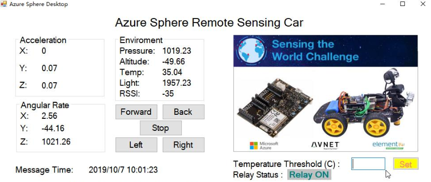
The desktop application is a .NET application. It is named as Azure Sphere Remote Sensing Car, which is built for message display and feedback control as follows.
Figure 8. The WinForm application running on desktop.
The device-to-cloud messages are handled and displayed on the Winform by ReceiveMessagesFromDeviceAsync as follows.
01.EventData eventData = await eventHubReceiver.ReceiveAsync();
02.if (eventData == null) continue;
03.byte[] data = eventData.GetBytes();
04.string connectionDeviceId = eventData.SystemProperties["iothub-connection-device-id"].ToString();
05.Debug.WriteLine("Message from " + connectionDeviceId);
06.if (connectionDeviceId != DeviceID)
07.    continue;
08.
09.string json = System.Text.Encoding.UTF8.GetString(data);
10.Debug.WriteLine(json);
11.//SensorDataObj = Deserialize<SensorData>(json);
12.SensorDataObj = JsonConvert.DeserializeObject<SensorData>(json);
13.gX.Invoke(new Action(() =>
14.{
15.    gX.Text = SensorDataObj.gX.ToString();
16.}));
17.gY.Invoke(new Action(() =>
18.{
19.    gY.Text = SensorDataObj.gY.ToString();
20.}));
21.gZ.Invoke(new Action(() =>
22.{
23.    gZ.Text = SensorDataObj.gZ.ToString();
24.    }));
25.aX.Invoke(new Action(() =>
26.{
27.    aX.Text = SensorDataObj.aX.ToString();
28.}));
29.aY.Invoke(new Action(() =>
30.{
31.    aY.Text = SensorDataObj.aY.ToString();
32.}));
33.aZ.Invoke(new Action(() =>
34.{
35.    aZ.Text = SensorDataObj.aZ.ToString();
36.}));
37.pressure.Invoke(new Action(() =>
38.{
39.    pressure.Text = SensorDataObj.pressure.ToString();
40.}));
41.altitude.Invoke(new Action(() =>
42.{
43.    altitude.Text = SensorDataObj.altitude.ToString();
44.}));
45.temperature.Invoke(new Action(() =>
46.{
47.    temperature.Text = SensorDataObj.temperature.ToString();
48.}));
49.light.Invoke(new Action(() =>
50.{
51.    light.Text = SensorDataObj.light.ToString();
52.}));
53.rssi.Invoke(new Action(() =>
54.{
55.    rssi.Text = SensorDataObj.rssi.ToString();
56.}));
57.msgTime.Invoke(new Action(() =>
58.{
59.    msgTime.Text = System.DateTime.Now.ToString();
60.}));
61.if (SensorDataObj.temperature >= TempThres)
62.{
63.    if (!cooleron)
64.    {
65.        SendCloudToDeviceMessageAsync("On");    //Power on Cooler
66.        sysstatus.Invoke(new Action(() =>
67.        {
68.            sysstatus.Text = "Relay ON";
69.        }));
70.        cooleron = true;
71.    }
72.}
73.else
74.{
75.    if (cooleron)
76.    {
77.        SendCloudToDeviceMessageAsync("Off");    //Power on Cooler
78.        sysstatus.Invoke(new Action(() =>
79.        {
80.            sysstatus.Text = "Relay OFF";
81.        }));
82.        cooleron = false;
83.    }
84.}
The cloud-to-device messages are triggered by Buttons as follows.
01.private void  buttonForward_Click(object sender, EventArgs e)
02.{
03.    SendCloudToDeviceMessageAsync("Forward");
04.}
05.
06.private void  buttonBack_Click(object sender, EventArgs e)
07.{
08.    SendCloudToDeviceMessageAsync("Back");
09.}
10.
11.private void  buttonStop_Click(object sender, EventArgs e)
12.{
13.    SendCloudToDeviceMessageAsync("Stop");
14.}
15.
16.private void  buttonLeft_Click(object sender, EventArgs e)
17.{
18.    SendCloudToDeviceMessageAsync("Left");
19.}
20.
21.private void  buttonRight_Click(object sender, EventArgs e)
22.{
23.    SendCloudToDeviceMessageAsync("Right");
24.}
25.
26.private void  buttonSpeedup_Click(object sender, EventArgs e)
27.{
28.    SendCloudToDeviceMessageAsync("Up");
29.}
30.
31.private void  buttonSlowdown_Click(object sender, EventArgs e)
32.{
33.    SendCloudToDeviceMessageAsync("Down");
34.}
5. Azure Cloud Integration
The services provided by Azure cloud, play a key role in data collecting, data processing, data storage and data visualization. This subsection contains all the services running on Azure cloud.
5.1 Azure IoT Hub
The Azure IoT Hub plays a central role. It acts as a bridge between the Azure Sphere devices and the Azure cloud services. Not only the device-to-cloud messages are collected by Azure IoT Hub to understand the real-time state of the MT3620 devices, but also the cloud-to-device commands and notifications are sent reliably to update the policies of sensor data collecting that are stored in the MT3620 device.
In the Azure Portal (https://portal.azure.com), click the on the "New" icon along the left to see all the services, then click the "Internet of Things" item and choose “IoT Hub”.
Complete the fields of “Name”, “Pricing Tier”, “IoT Hub Units”, “Device-to-Cloud Partitions”, “Resource group” and “location”, then click the "Create" button. It should be noted that “F1 Free” Pricing is enough for this project. And we’d better choose the local location of the service.
Wait for the new IoT hub to show as "Online". When it is ready, open the blade of the new IoT hub, take note of the URI and select the key icon at the top to access to the shared access policy settings.
Select the Shared access policy called iothubowner, and take note of the Primary key and connection string in the right blade. We may copy these into a text file for future use.
For more information, we can refer to this doc online: Create an IoT hub using the Azure portal (https://docs.microsoft.com/en-us/azure/iot-hub/iot-hub-create-through-portal ).
5.2 Authenticate the Avnet Start Kit with Device Explorer
Communication between Azure IoTHub and devices is secured. On Windows, we can use Device Explorer app to complete this Authentication process. A pre-built version of the Device Explorer application for Windows can be downloaded by clicking on this link: https://github.com/Azure/azure-iot-sdk-csharp/releases/tag/2019-1-4 (Scroll down for SetupDeviceExplorer.msi). The default installation directory for this application is "C:\Program Files (x86)\Microsoft\DeviceExplorer".
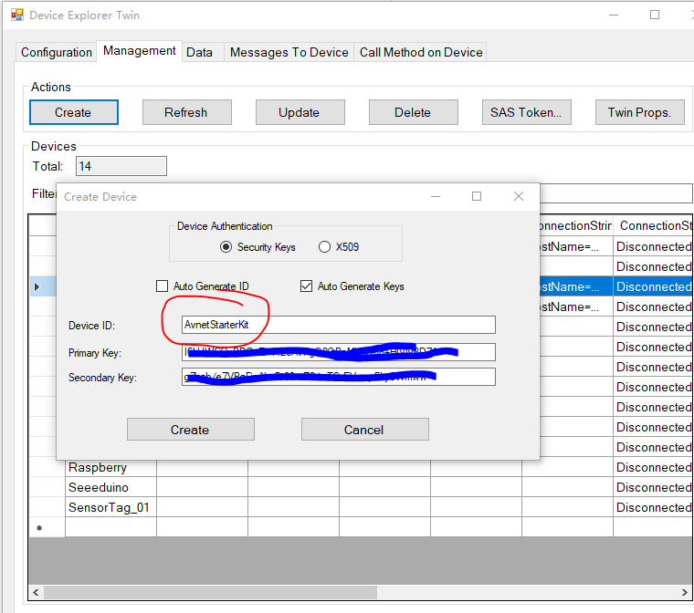
Open the Device Explorer app and fill the IoT Hub Connection String field with the connection string of the IoT Hub that we created and click on Update. Go to the Management tab and click on the Create button. The Create Device popup will be displayed. Fill the Device ID field with a new Id for your device (AvnetStarterKit for example) and click on Create as follows.
Figure 9. Authenticate the Avnet Starter Kit with Device Explorer
When the device identity is created, it will be displayed in the grid. Right click on the identity we created, select Copy connection string for selected device and save the value by copying to clipboard, since it will be required to connect the hardware with the IoT Hub.
5.3 Update Azure IoTHub connection string
Download the source code from GitHub repository (https://github.com/shijiong/AzureSphereRemoteSensingCar/tree/master/AvnetAzureSphereSK_OLED). Open the solution with Visual Studio, navigate to “connection_strings.h”, update the connetion string as shown in Figure 10.
Figure 10. Update Azure IoTHub connection string
5.4 Create Azure Stream Analytics Job
Azure Stream Analytics is used in this project to filter the sensor data that gathered by IoTHub, and stream the data to PowerBI. The new Stream Analytics is created as follows.
In the Azure Portal (https://portal.azure.com), click the on the "New" icon along the left to see all the services, then click the "Internet of Things" item and choose “Stream Analytics job”.
Complete the fields of “Job Name”, “Resource group” and “location”, then click the "Create" button. Wait for the new Stream Analytics to show as "Online".
Now, it’s time to config the Stream Analytics Job. First, in the Inputs window, we choose IoT Hub, and in the IoT Hub Settings screen, we complete the following information:
- Input Alias: AvnetData
- Subscription: Use IoT Hub from Current Subscription
- Choose an IoT Hub: input the name used during the IoT Hub creation
- IoT Hub Shared Access Policy Name: iothubowner
- IoT Hub Consumer Group: powerbi
- Click Next, and then Complete (leave the Serialization settings as they are).
To set up the output, go to the Stream Analytics Job's OUTPUTS tab, and click the ADD AN OUTPUT link. In the Add an output to your job popup, select the POWER BI option and the click the Next button. In the following screen you will setup the credentials of your Power BI account to allow the job to connect and send data to it. Click the Authorize Now link.
To set up the Query configuration, go to the Stream Analytics Job QUERY tab and replace the query with the following statement:
1.SELECT
2.    *
3.INTO
4. [AvnetStartKit]
5.FROM
6. [MT3620]
It should be noticed that we just select all the data from IoTHub to PowerBI. Click on the SAVE button and YES in the confirmation dialog. Now that the job is configured, the START button is enabled. Click the button to start the job and then select the JOB START TIME option in the START OUTPUT popup. After clicking OK the job will be started. Once the job starts it creates the Power BI datasource associated with the given subscription.
5.5 Config PowerBI Dashboard
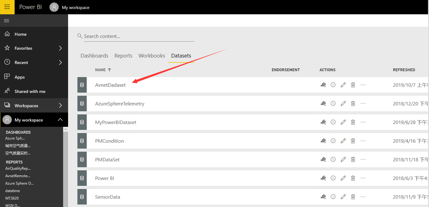
Now that the datasource is created, go back to Power BI session, and find My Workspace by clicking the Power BI link. After some minutes of the job running you will see that the dataset that you configured as an output for the Job, is now displayed in the Power BI workspace Datasets section in Figure 11.
Figure 11. Power BI workspace Datasets
Please note that the Power BI dataset will only be created if the job is running and if it is receiving data from the IoT Hub input, so check that the hardware is working and sending data to Azure to ensure that the dataset be created. To check if the Stream Analytics job is receiving and processing data you can check the Azure Management Stream Analytics monitor.
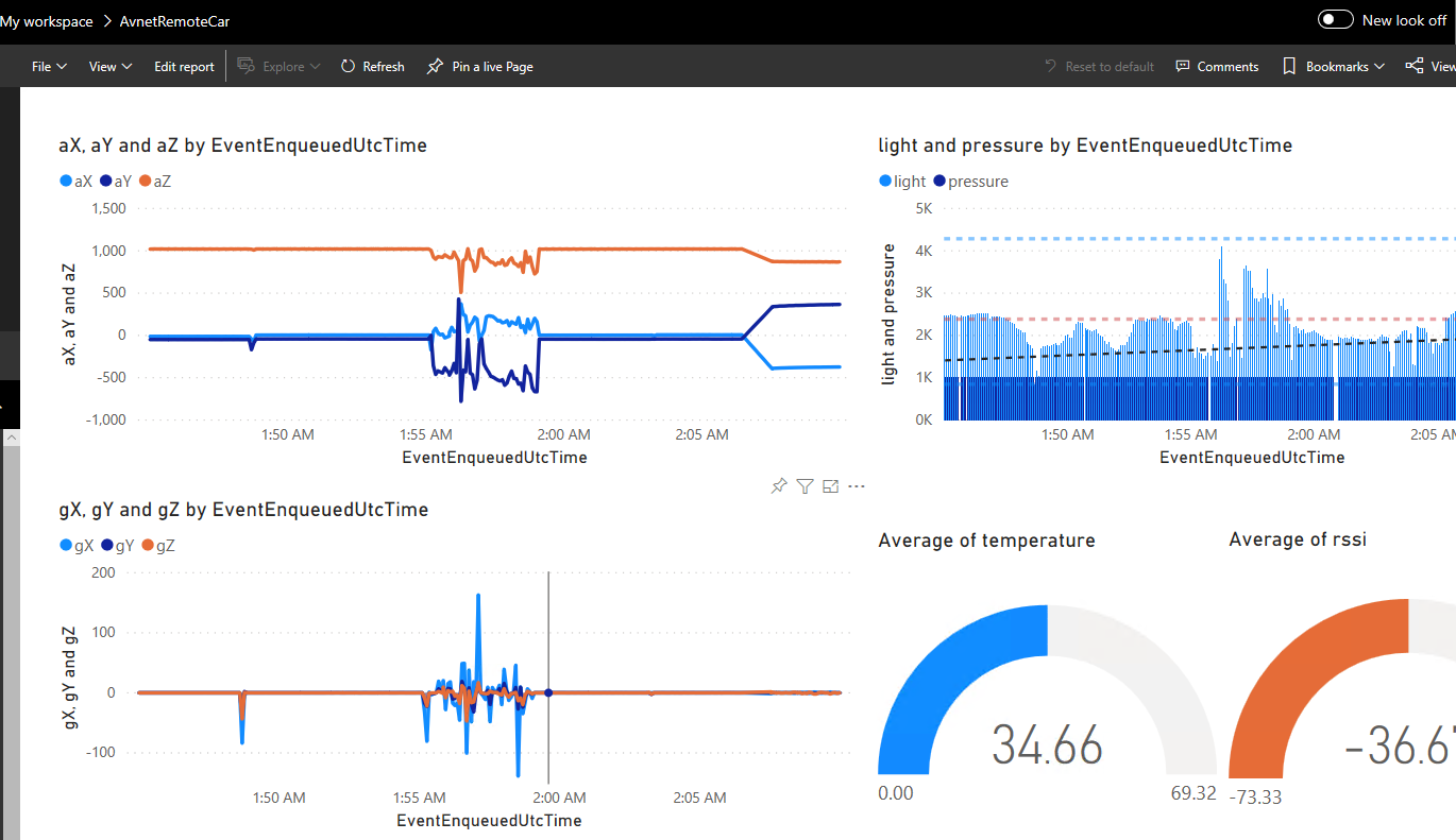
Once the datasource becomes available you can start creating reports. To create a new Report, click on the Power BI datasource.
The Report designer will be opened showing the list of fields available for the selected datasource and the different visualizations supported by the tool. Here we choose real-time sensor date and the processing time. Now the report is almost ready. Click the SAVE button and set Campus Environment as the name for the report as follows.
Figure 12. Power BI Report designer
5.6 Browse PowerBI Data on Mobile Device
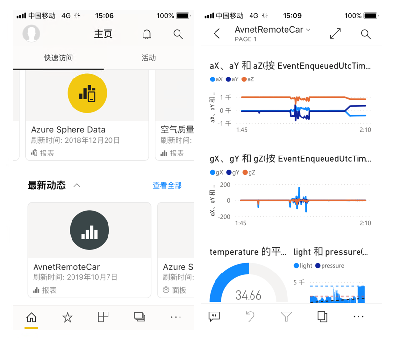
With Power BI Desktop (https://powerbi.microsoft.com/en-us/desktop/), we can get the data from Power BI Web and display the data report that we create above on desktop PC.With Power BI application on iOS or Android, we can get the data from Power BI Web and display the data report on mobile phone.
Figure 13. Power BI Mobile
6. Appendix
6.1 Build and Monitor the application
Download the source project from Github: https://github.com/shijiong/AzureSphereSecurityGateway/tree/master/AvnetAzureSphereSK_OLED. Make sure the following configurations.
- Open the build_options.h file in this IDE's editor and check:
- Line #5: must be commented-out (ie. remove comment characters if present at line start of //#define IOT_CENTRAL_APPLICATION ).
- Line #8: must be enabled (ie. #define IOT_HUB_APPLICATION )
2. The connection string in connection_strings.h should be replaced with your own device connection string.
3. In app_manifest.json file, "ISU0" should be set in “Uart” section and "****.azure-devices.net" (your own IoTHub) should be configured in “AllowedConnections” section.
6.2 Monitor the output of the Visual Studio IDE
The debug information will be displayed in the output windows of Visual Studio. When we click Forward button on the WinForm application, the message will be sent by Cloud to Device message and it will be processed by MT3620. The raw information will be shown as in Figure 14. As we can see, the message is well received and the corresponding UART Hex data is sent to Arduino for car control.
Figure 14. Output Window of Visual Studio
6.3 Monitor the messages with Device Explorer
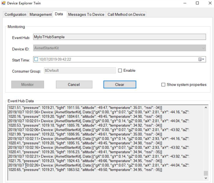
Once the messages are sent successfully to Azure IoTHub by Avnet Start Kit, the information can be monitored by Device Explorer. The raw messages are shown as in Figure 15.
Figure 15. Message captured by Device Explorer
6.4 Monitor the output of the WinForm Application
As soon as the application starts, the communication between the desktop and the Azure IoTHub is established. And the Device to Cloud messages are displayed on the output window as in Figure 16.
Figure 16. Message of the WinForm Application
7. Summary
In this project, we build a remote sensing car with Azure Sphere, Azure IoT Cloud Services, and WinForm desktop application. We focused on the following three aspects. Firstly, featured by Azure Sphere device and Azure cloud services, an integration of hardware, software and services was designed, deployed and tested. Secondly, the hardware prototypes including Avnet Azure Sphere Starter Kit and Arduino Car model were designed and implemented. Thirdly, the programs for hardware devices, the configurations for cloud services as well as the PowerBI applications were designed and tested.
Special Thanks
Thanks to Peter Fenn and Brian Willess, the program for Avnet Azure Sphere Start Kit is built on the basis of their work "Avnet Azure Sphere Starter-Kit: Advanced Tutorial."
Thanks to Avnet and Microsoft, you provided me with the Azure Sphere Starter Kit to help making this project into reality!
Source Code
The source code of this project is published on GitHub: https://github.com/shijiong/AzureSphereRemoteSensingCar
Note
This project is first published on Element14 community, which is designed for "Sensing the World Challenge". In this Version, we add the "Speed Control". Please refer to the source code page on github for more details.
Resources
- Dev Kit: Avnet Azure Sphere MT3620 Starter Kit
- OLED Display: 128x64 Yellow Blue SSD1306 I2C OLED Display [optional]
- Micro Controller: Arduino UNO
- Car Model: A car model
- Tutorial: Avnet Azure Sphere Starter-Kit: Advanced Tutorial
- Docs: Create an IoT hub using the Azure portal
See Also
Azure IoT Docs: Azure IoTHub
Azure Sphere Docs: Azure Sphere
My Projects on Hackster: Jiong Shi
