The IoT Journey: Additional Peripheral Protocols
In the last post of this series, I discussed digital signaling and hardware interrupts. The purpose of these posts is to educate on the basics of IoT technologies so that you will have a foundation to work from in order to build new IoT projects. In this post, we will discuss the concept of Pulse-Width Modulation (PWM) and how to use PWM to drive a tri-color LED with code on the Raspberry Pi.
Pulse Width Modulation
When controlling physical “things” from electronics, you have to be able to do more than simply power on and off a device, or react to the press of a button. The challenge there is that digital signals are either “on” or “off”, and buttons are either pressed or not. When working with electronic circuitry, one technique used to encode a message into a digital signal is called Pulse Width Modulation, or PWM. Basically what this means is that you define a “width” of the “on” signal (the amount of time that the signal is on) as equal to a binary value, and then you define the amount of time that you will “read” the total signal to obtain the message.
Probably the most common use of PWM in electronics is controlling the speed of a motor. Instead of using an analog circuit and adjustable resistor (which can generate a lot of heat and wasted energy), PWM is used to control the “duty cycle” of the motor (the amount of time that full power is applied versus the amount of time power is off). A simplistic example would be if we wanted to run a motor at 50% of it’s maximum speed, we could set the duty cycle to 50%, meaning that the PWM signal would be on 50% of the time and off 50% of the time.
There are many other examples of using PWM in electronics, and one of the easiest to work with is the multi-color LED light. A multi-color LED, or RGB LED, has a common cathode (or anode, depending on type) and then 3 inputs representing each of the primary colors. By using PWM and controlling the amount of time power is applied to each of the primary color inputs, we can create virtually unlimited output colors on the LED.
The Raspberry Pi 3 has 2 available PWM hardware outputs, but one of those is shared with the audio out, so in practice there is only a single channel available. Given this, projects that require more than a single PWM channel (such as the example above of an RGB LED) utilize a software library that “bit bangs” the output of a GPIO pin to create the PWM signal. This works well for LEDs and servo motors, where the use of the PWM signal is limited, but it’s much harder to implement when controlling a motor that requires a more constant PWM signal ( this is because for the duration of the PWM signal, the CPU is effectively latched performing that task).
For the purposes of this example, we’ll control an RGB LED from the Raspberry Pi, using the SoftPWM capabilities exposed in the WiringPi library that we’ve used in previous examples…
Step One – Wire the Circuit
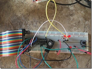
Since we will require 3 GPIO channels, we’ll choose GPIO Pins 23, 24 and 25 (physical pins 16, 18 and 22) since they are convenient and aren’t used in the ISR solution that we created in the previous post. The Red pin will connect to GPIO 23, the Green pin to GPIO 24 and the Blue pin to GPIO 25. Connect the ground (-) pin to GND on the breadboard.
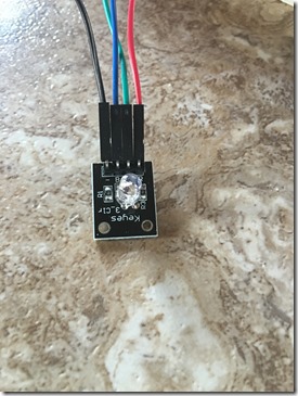
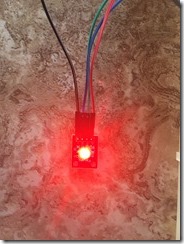
If you purchased the Sunfounder Sensor kit mentioned in previous posts, you’ll have an RGB LED that is already mounted to a circuit board with headers, otherwise you’ll need to obtain one and connect wires to the leads in order to plug it into the breadboard properly. The LED assembly looks like this:
The breadboard configuration will look like this:
Once the circuit is wired, we’re ready to extend the previous code solution to include the RGB LED.
Step Two – Develop the Solution
For the sake of simplicity, we’ll simply extend the previous button solution that we created and add the RGB LED. We will write code that will toggle the state of the LED between Red, Green and Blue as the button is pressed.
The flow of the program is basically:
- Initialize the SoftPWM library and connect each of the GPIO outputs to the appropriate color pin on the LED
- Initialize the ISR and set the callback method used
- Ensure that the RGB LED is off
- Wait for either a button press or a keyboard press
- If a button press is detected, toggle the solitary LED, and then check the current state of the RGB LED and then toggle through the color choices
- If a keyboard press is detected, close the PWM library and exit the program
Open the ISR solution in Visual Studio that we previously created (See the previous post in this series) and add the supporting constants:
Then add code to initialize the SoftPWM Library. We will use the default of 100 microseconds for the pulse width to balance CPU utilization with PWM functionality.
Then add a method to the class that sets the RGB LED saturation values:
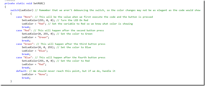
Once that is done, add a method that detects the current state of the RGB LED and toggles it appropriately. (In this example we’re just using Red, Green and Blue as colors, however you can mix/match the RGB values to create any color combination that you want).
Finally, add code to the ISR method that invokes the SetRGB() method.
This will ensure that the LED switches through the RGB colors (or colors that you define) with a button press. Keep in mind that we are not debouncing the switch, so you will likely see some spurious color changes when you press the button.
The complete program.cs code is as follows:
using System;
using System.Threading.Tasks;
using WiringPi;
namespace ISR
{
class Program
{
const int redLedPin = 29; // GPIO 5, physical pin 29
const int buttonPin = 31; // GPIO 6, physical pin 31
const int rgbLedR = 16; // GPIO 23, physical pin 16
const int rgbLedG = 18; // GPIO 24, physical pin 18
const int rgbLedB = 22; // GPIO 25, physical pin 22
static string LedColor = "None"; // This is just a string variable that tells us what color the RGB LED is currently
// The color saturation value is how "on" that particular color is. So when the redvalue is 255 and green and blue are 0, the
// Led will be Red. If the RedValue is 255 and GreenValue is 255, then the resulting color will be Red+Green or Yellow
// If Red is 0 and Green and Blue are both 255, then the resulting color will be Blue + Green or Cyan.
// See the RGB Model Wikipedia for more info: https://en.wikipedia.org/wiki/RGB_color_model
static void buttonPress()
{
if (GPIO.digitalRead(redLedPin) == (int)GPIO.GPIOpinvalue.Low) // Check to see if LED is on
GPIO.digitalWrite(redLedPin, (int)GPIO.GPIOpinvalue.High); // If so, turn it off
else
GPIO.digitalWrite(redLedPin, (int)GPIO.GPIOpinvalue.Low); // Otherwise turn it on
SetRGB(); // Light the RGB LED with the appropriate color
}
static void Main(string[] args)
{
Console.WriteLine("Initializing GPIO Interface");
if (Init.WiringPiSetupPhys() < 0) //Initialize the GPIO Interface with physical pin numbering
{
throw new Exception("Unable to Initialize GPIO Interface"); // Any value less than 0 represents a failure
}
GPIO.pinMode(redLedPin, (int)GPIO.GPIOpinmode.Output); // Tell the Pi we will be writing to the GPIO
GPIO.digitalWrite(redLedPin, (int)GPIO.GPIOpinvalue.Low); // Turn LED On
GPIO.SoftPwm.Create(rgbLedR, 0, 100); // Setup the RGB LED pins as PWM Output and set the Pulse Max duration of 100 microseconds.
GPIO.SoftPwm.Create(rgbLedG, 0, 100); // This is software-based PWM since the Pi only has a single PWM hardware channel
GPIO.SoftPwm.Create(rgbLedB, 0, 100);
Console.WriteLine("Initializing Interrupt Service Routine");
// We will fire the interrupt on the falling edge of the button press. Note that we are not "debouncing" the switch, so we will likely
// see some extra button presses during operation
if (GPIO.PiThreadInterrupts.wiringPiISR(buttonPin, (int)GPIO.PiThreadInterrupts.InterruptLevels.INT_EDGE_FALLING, buttonPress) < 0) // Initialize the Interrupt and set the callback to our method above
{
throw new Exception("Unable to Initialize ISR");
}
Console.WriteLine("Press the button to toggle LED or press any key (and then press button) to exit");
Console.ReadKey(); // Wait for a key to be pressed
GPIO.digitalWrite(redLedPin, (int)GPIO.GPIOpinvalue.High); // Turn off the static LED
GPIO.SoftPwm.Stop(rgbLedR); // Turn off the RGB LED
GPIO.SoftPwm.Stop(rgbLedG);
GPIO.SoftPwm.Stop(rgbLedB);
}
private static void SetRGB()
{
switch(LedColor) // Remember that we aren't debouncing the switch, so the color changes may not be as elegant as the code would show
{
case "None": // This will be the value when we first execute the code and the button is pressed
SetLedColor(255, 0, 0); // Turn the LED On Red
LedColor = "Red"; // Set the variable to Red so we know what color is showing
break;
case "Red": // This will happen after the second button press
SetLedColor(0, 255, 0); // Set the color to Green
LedColor = "Green";
break;
case "Green": // This will happen after the third button press
SetLedColor(0, 0, 255); // Set the color to Blue
LedColor = "Blue";
break;
case "Blue": // This will happen after the fourth button press
SetLedColor(255, 0, 0); // Set the color to Red
LedColor = "Red";
break;
default: // We should never reach this point, but if we do, handle it
LedColor = "None";
break;
}
}
private static void SetLedColor(int r, int g, int b) // Pulse the RGB pins with the appropriate saturation values
{
GPIO.SoftPwm.Write(rgbLedR, r);
GPIO.SoftPwm.Write(rgbLedG, g);
GPIO.SoftPwm.Write(rgbLedB, b);
}
}
}
Now that the code is developed, build it and fix any errors that you find. Once it is built without error, we can deploy it to the Pi and test.
Step Three Deploy and Execute the Code
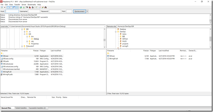
Using a file transfer program (as mentioned before, I use FileZilla) connect to the Pi and copy the ISR.exe and WiringPi.dll files to the Pi. Overwrite the files that you previously copied.
Once the files are copied, you can execute the ISR.exe program by typing the command sudo mono ISR.exe:
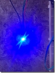
Press the button several times and then note that the RGB LED switches through the colors.
Congrats! You now have developed and deployed a solution that utilizes Pulse Wide Modulation to control an LED!!
