ESP8266 Wifi With Arduino Uno and Nano
If you are trying to add Wifi connectivity to an existing Arduino project or have serious aspirations for developing a Internet of Things (IoT) solution, Arduino + ESP8266 wifi module is one of the top choices. Especially the Nano because it is super cheap (<$3) and is very small in size. Using some sort of web-server directly on ESP8266 (e.g. via Lua) doesn't cut it due to the lack of IO pins on ESP8266. You can get a full IoT node out at under $12 with a few sensors, Arduino Nano and a ESP9266 module (excluding the power supply).
Inspite of a plethora of posts online it turned out to be very hard for me to get this to combination to work. I spent atleast 3-4 days until I actually got this right. The main problem I see is that a lot of the solutions online are actually down-right incorrect, not-recommended or for other similar boards (e.g. Arduino Mega). Also there are a few gotchas that were not commonly called out. Before I start let me get all of those out of the way
- Arduino Uno/Nano is very different from say Mega which can supply more current and have different number of UART. The steps to make a Uno and Nano work is different from them.
- Power Supply
- ESP8266 is powered by 3.3V and NOT 5V. So you cannot have a common power supply between Arduino and ESP8266
- ESP8266 draws way more current (200mA) then it can be supplied by the 3.3v pin on the Uno/Nano. Don’t even try them, I don't buy anyone who claims to have done this. Maybe they have some other high power variant of Arduino (Mega??) that can do this.
- So you either use a 3.3v 1A power supply to ESP8266 with common ground with the 5V powering Arduino, or you use a step down 5v to 3.3v (e.g. like here).
- Arduino <-> ESP8266
- All the ESP8266 I bought came with the UART serial IO speed (BAUD) set to 115200. Now the problem is that Uno/Nano has only one HW serial, which is set to be used for communicating with the PC over USB with which you are debugging. You can use any other two IO pins to talk to the ESP8266 using SoftwareSerial, but it does not support that high a BAUD speed. If you try 115200 to communicate with Arduino <-> ESP8266 you will get garbage. A lot of articles online show a setup with Arduino Mega which does have two HW serial IO using which you can easily get 115200 and more. So you need to dial the ESP8266 settings to move the communication speed to a more manageable BAUD of 9600
- Arduino IO pins have 5V and ESP8266 accepts 3.3 v (max 3.6). I have seen people directly connect the pins but you are over driving the ESP8266. If it doesn’t burn out immediately (the cheaper ones does), it will burn out soon. I suggest you use a voltage divider using simple resistor to have Arduino transmission (TX) drive ESP8266 receive (RX)
- For some strange reason D2/D3 pins on Arduino Nano didn’t work for me for the communicating with ESP8266. I have no explanation for this and it happened on two separate Nano. The Arduino would just read a whole bunch of garbage character. So I had to move to the pins 8/9.
- In spite of whatever I did, garbage characters would still come in sometimes. So I wrote a small filter code to ignore them
Things you need
- ESP8266
- Arduino Nano
- Power supply 5v and 3.3v
- Resistors 1K, 2.2K, 10K
- FTDI USB to serial TTL adapter. Link (optional, see below)
Setting up ESP8266
 As mentioned above I first set the ESP8266 BAUD rate to 9600. If yours is already 9600 then nothing to be done, if not you need to make the following connection
PC (USB) <-> FTDI <-> ESP8266
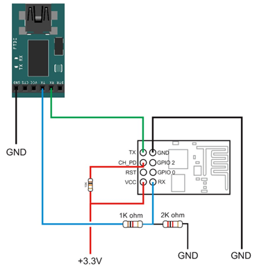
Then using specific AT commands from the PC set the 9600 BAUD rate on the ESP8266. I used the following circuit. Where the connections are as follows
FTDI TX –> Via voltage divider (to move 5v to ~3.3v) to ESP8266 RX (blue wire)
FTDI RX –> Directly to ESP8266 TX (green wire). A 3.3v on Nano I/0 pin will be considered as 1.
FTDI GND to common ground (black)
ESP8266 GND to common GND (black)
ESP8266 VCC to 3.3v (red)
ESP8266 CH_PD to 3.3v via a 10K resistor (red)
Power supply GND to common GND
PC to FTDI USB.
One that is set bring up Arduino IDE and do the following using the menu
- Tools –> Port –>COM{n}. For me it was COM6
- Then Tools –> Serial monitor
In the serial monitor ensure you have the following set correctly. The BAUD should match the preset BAUD of your ESP8266. If you are not sure, use 115200 and type the command AT. If should return OK, if not try changing the BAUD, until you get that.
Then change the BAUD rate by using the following command, and you should get OK back
AT+CIOBAUD=9600
After that immediately change the BAUD rate in the serial monitor to be 9600 baud as well and issue a AT command. You should see OK. You are all set for the ESP8266.
Setting up Arduino Nano + ESP8266
This step should work for Uno as well. Essentially make the same circuit as above, but now instead of FTDI use an Arduino. I used pins 8 and 9 on Arduino for the RX and TX respectively.
Debugging and Setup WIFI
Even though I could easily run AT commands with the PC <->FTDI <-> ESP8266, I ran into various issues while doing the same programmatically in PC <->Arduino <-> ESP8266 setup. So I wrote the following very simple code to pass on commands I typed in the PC via the Arduino to the ESP8266 and reverse for outputs.
The code is at GitHub as https://github.com/bonggeek/Samples/blob/master/Arduino/SerialRepeater.ino
 #include <SoftwareSerial.h>
SoftwareSerial softSerial(8, 9); // RX, TX

void setup()
{
  uint32_t baud = 9600;
  Serial.begin(baud);
  softSerial.begin(baud);
  Serial.print("SETUP!! @");
  Serial.println(baud);
}

void loop()
{
    while(softSerial.available() > 0)
    {
      char a = softSerial.read();
      if(a == '\0')
        continue;
      if(a != '\r' && a != '\n' && (a < 32))
        continue;
      Serial.print(a);
    }

    while(Serial.available() > 0)
    {
      char a = Serial.read();
      Serial.write(a);
      softSerial.write(a);
    }
}
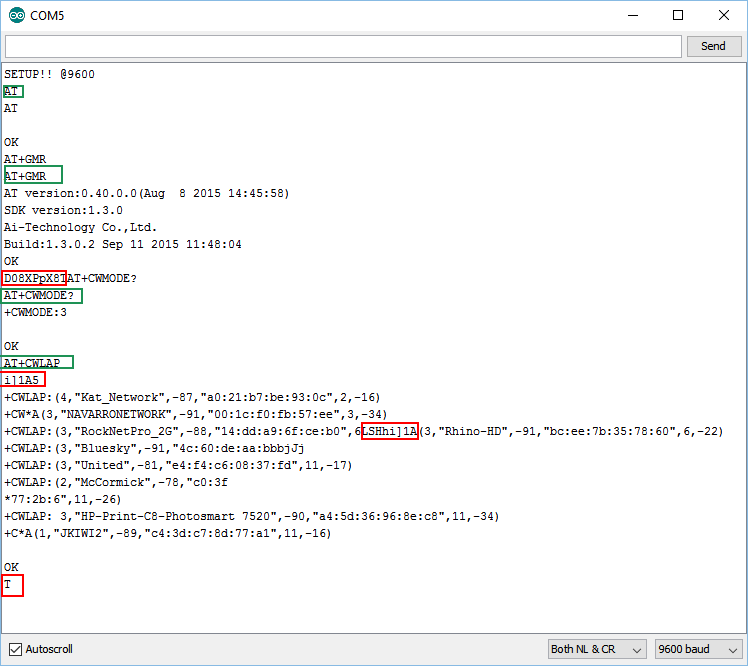
With this code built and uploaded to Arduino I launched the Serial monitor on my PC. After that I could type commands in my Serial Monitor and have the Arduino pass that only ESP8266 and read back the response. I can still see some junk chars coming back (in RED). All commands are in Green and could easily enumerate all Wifi in range using AT+CWLAP and even connect to my Wifi.


