How to: Create a Geometry-Based Gradient Shader
Note
This article applies to Visual Studio 2015. If you're looking for the latest Visual Studio documentation, see Visual Studio documentation. We recommend upgrading to the latest version of Visual Studio. Download it here
This document demonstrates how to use the Shader Designer and the Directed Graph Shader Language to create a geometry-based gradient shader. This shader scales a constant RGB color value by the height of each point of an object in world space.
This document demonstrates these activities:
Adding nodes to a shader graph
Setting node properties
Disconnecting nodes
Connecting nodes
Creating a geometry-based gradient shader
You can implement a geometry-based shader by incorporating the position of the pixel into your shader. In shading languages, a pixel contains more information than just its color and location on a 2-D screen. A pixel—known as a fragment in some systems—is a collection of values that describe the surface that corresponds to a pixel. The shader that's described in this document utilizes the height of each pixel of a 3-D object in world space to affect the final output color of the fragment.
Before you begin, make sure that the Properties window and the Toolbox are displayed.
To create a geometry-based gradient shader
Create a DGSL shader to work with. For information about how to add a DGSL shader to your project, see the Getting Started section in Shader Designer.
Disconnect the Point Color node from the Final Color node. Choose the RGB terminal of the Point Color node, and then choose Break Links. This makes room for the node that's added in the next step.
Add a Multiply node to the graph. In the Toolbox, under Math, select Multiply and move it to the design surface.
Add a Mask Vector node to the graph. In the Toolbox, under Utility, select Mask Vector and move it to the design surface.
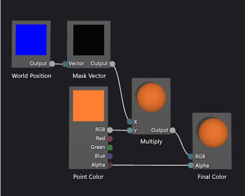
Specify mask values for the Mask Vector node. In Select mode, select the Mask Vector node, and then in the Properties window, set the Green / Y property to True, and then set the Red / X, Blue / Z and Alpha / W properties to False. In this example, the Red / X, Green / Y, and Blue / Z properties correspond to the x, y, and z components of the World Position node, and Alpha / W is unused. Because only Green / Y is set to True, only the y component of the input vector remains after it is masked.
Add a World Position node to the graph. In the Toolbox, under Constants, select World Position and move it to the design surface.
Mask the world space position of the fragment. In Select mode, move the Output terminal of the World Position node to the Vector terminal of the Mask Vector node. This connection masks the position of the fragment to ignore the x and z components.
Multiply the RGB color constant by the masked world space position. Move the RGB terminal of the Point Color node to the Y terminal of the Multiply node, and then move the Output terminal of the Mask Vector node to the X terminal of the Multiply node. This connection scales the color value by the height of the pixel in world space.
Connect the scaled color value to the final color. Move the Output terminal of the Multiply node to the RGB terminal of the Final Color node.
The following illustration shows the completed shader graph and a preview of the shader applied to a sphere.
Note
In this illustration, an orange color is specified to better demonstrate the effect of the shader, but because the preview shape has no position in world-space, the shader cannot be fully previewed in the Shader Designer. The shader must be previewed in a real scene to demonstrate the full effect.

Certain shapes might provide better previews for some shaders. For information about how to preview shaders in the Shader Designer, see Previewing shaders in Shader Designer
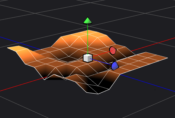
The following illustration shows the shader that's described in this document applied to the 3-D scene that's demonstrated in How to: Model 3-D Terrain. The intensity of the color increases with the height of the point in the world.

For more information about how to apply a shader to a 3-D model, see How to: Apply a Shader to a 3-D Model.
See Also
How to: Apply a Shader to a 3-D Model How to: Export a Shader How to: Model 3-D Terrain How to: Create a Grayscale Texture Shader Shader Designer Shader Designer Nodes