Raspberry PI 2 and analog input
Compare to Arduino, Raspberry PI 2 doesn’t have analog pins and even PWM pins. If you check IoT extension for Universal Windows Platform you will discover three sets of classes: I2C, SPI and GPIO. The last one allows to use Raspberry GPIO for sending/receiving high or low voltage only. So, if you want to create a drone or cool robot based on Raspberry Pi 2 and powered by Windows 10, you need to answer the following questions:
- How to read analog signals;
- How to emulate PWM (pulse width modulation);
- How to read digital signals from various digital sensors (if these signals are not LOW or HIGH);
In this post I am going to answer the first question.
Because GPIO of Raspberry doesn’t have any PWM features we need to use external convertors which help us to transform analog signal to digital. I would recommend to use convertors from Microchip Technology and there is the great section of different chips: MCP3002, MCP3008, MCP3208 etc. I bought MCP3008 because it supports up to 8 channels and represent analog data in 10 bits format. Because Arduino and Netduino use the same format (from 0 to 1024) I am used to using 10 bits.
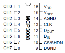
MCP3008 works based on SPI bus, so we should use SPI bus on Raspberry. In order to do it I connected CLK leg of the chip to pin SPI0 CSLK (19), D(out) leg to SPI0 MISO pin (21), D(in) leg to SPI0 MOSI (23) and CS/SHDN to SPI0 CS0 (24). V(dd) and V(ref) legs I connected to power and DGND to the ground.
I have analog photoresistor sensor only. So, I used just channel 0 and connect signal leg of the sensor to CH0.
Below you can find my code which you can copy and paste to MainPage.xaml.cs of your Universal application. I didn’t make any interface and just used Debug class to print sensor’s data to Output window:
 byte[] readBuffer = new byte[3];
byte[] writeBuffer = new byte[3] { 0x06, 0x00, 0x00 };

private SpiDevice spi;

private DispatcherTimer timer;

private void Timer_Tick(object sender, object e)
{
 spi.TransferFullDuplex(writeBuffer, readBuffer);
 int result = readBuffer[1] & 0x07;
 result <<= 8;
 result += readBuffer[2];
 result >>= 1;
 Debug.WriteLine(result.ToString());
}

protected async override void OnNavigatedTo(NavigationEventArgs e)
{
 await StartSPI();
 this.timer = new DispatcherTimer();
 this.timer.Interval = TimeSpan.FromMilliseconds(500);
 this.timer.Tick += Timer_Tick;
 this.timer.Start();
 base.OnNavigatedTo(e);
}

private async Task StartSPI()
{
 try
 {
 var settings = new SpiConnectionSettings(0);
 settings.ClockFrequency = 5000000;
 settings.Mode = SpiMode.Mode0;

 string spiAqs = SpiDevice.GetDeviceSelector("SPI0");
 var deviceInfo = await DeviceInformation.FindAllAsync(spiAqs);
 spi = await SpiDevice.FromIdAsync(deviceInfo[0].Id, settings);
 }
 catch (Exception ex)
 {
 throw new Exception("SPI Initialization Failed", ex);
 }
}
Comments
Anonymous
June 08, 2015
Care to explain the Timer_Tick code in more detail? I understand what is happening, but not why. For example, I've seen similar code on huckster.io but with slightly different values and no bit shifting.Anonymous
March 16, 2016
can we make digital to analog and analog to digital on same commponent on raspberry pi 2?- Anonymous
March 17, 2016
Raspberry 2 doesn't support DAC or ADC features. So, you have to buy two different ICs (integrated circuits) in order to use these features. It's very hard to advice, which one you have to use because there are hundreds different ICs. It depends on your project. I would recommend The Art of Electronics book. There are couple chapters about ADC/DAC with recommendations.
- Anonymous
Anonymous
March 16, 2016
dear plz reply i want to design my own home screen using raspberry pi 2 plz help me.Anonymous
April 30, 2016
Will this method work with the Pi Zero? If so, please elaborate, Thanks


