Define a Domain-Specific Language
To define a domain-specific language (DSL), you create a Visual Studio solution from a template. The key part of the solution is the DSL Definition diagram, which is stored in DslDefinition.dsl. The DSL Definition defines the classes and shapes of the DSL. After you modify and adding to these elements, you can add program code to customize the DSL in more detail.
If you are new to DSLs, we recommend that you work through the DSL Tools Lab, which you can find in this site: Visualization and Modeling SDK
Selecting a Template Solution
To define a DSL, you must have installed the following components:
- Visual Studio
- Visual Studio extension development workload (includes the Visual Studio SDK)
- Modeling SDK (install it as an individual component in Visual Studio)
Note
The Text Template Transformation component is automatically installed as part of the Visual Studio extension development workload. You can also install it from the Individual components tab of Visual Studio Installer, under the SDKs, libraries, and frameworks category. Install the Modeling SDK component from the Individual components tab.
To create a new domain-specific language, you create a new Visual Studio solution using the Domain-Specific Language project template.
To create a DSL solution
Create a new Domain-Specific Language project.
The Domain-Specific Language Wizard opens and displays a list of template DSL solutions.
Click each template to see a description. Choose the solution that most closely resembles what you want to create.
Each DSL template defines a basic working DSL. You will edit this DSL to fit your own requirements.
Click each sample for more information.
Select Task Flow to create a DSL that has swimlanes. Swimlanes are vertical or horizontal partitions of the diagram.
Select Component Models to create a DSL that has ports. Ports are small shapes on the edge of a larger shape.
Select Class Diagrams to define a DSL that has compartment shapes. Compartment shapes contain lists of items.
Select Minimal Language in other cases, or if you are uncertain.
Select Minimal WinForm Designer or Minimal WPF Designer to create a DSL that is displayed on a Windows Forms or WPF surface. You will have to write code to define the editor. For more information, see the following topics:
Enter a file name extension for your DSL in the appropriate wizard page. This is the extension that files containing instances of your DSL will use.
Choose a file name extension that is not associated with any application in your computer, or in any computer where you want to install the DSL. For example, docx and htm would be unacceptable file name extensions.
The wizard will warn you if the extension that you have entered is being used as a DSL. Consider using a different file name extension. You can also reset the Visual Studio SDK Experimental instance to clear out old experimental designers. In the Windows Start menu, type reset the Visual Studio, and then run the Reset the Microsoft Visual Studio Experimental Instance command matching your version of Visual Studio.
You can either adjust the settings on the other pages, or leave the default values.
Click Finish.
The wizard creates a solution that contains two or three projects, and generates code from the DSL definition.
The user interface now resembles the following picture.
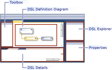
This solution defines a domain specific language. For more information, see Overview of the Domain-Specific Language Tools User Interface.
Test the Solution
The template solution provides a working DSL, which you can modify or use as it is.
To test the solution, press F5 or CTRL+F5. A new instance of Visual Studio opens in experimental mode.
In the new instance of Visual Studio, in Solution Explorer, open the Sample file. It opens as a diagram, with a toolbox.
If you run a solution that you have created from the Minimal Language template, your experimental Visual Studio will resemble the following example:
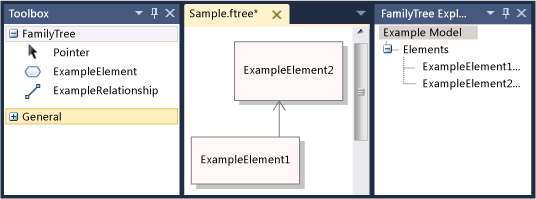
Experiment with the tools. Create elements and connect them.
Close the experimental instance of Visual Studio.
Note
When you have modified the DSL, you will no longer be able to see the shapes on the Sample test file. However, you will be able to create new elements.
Modifying the template DSL
Rename and keep some or all of the domain classes and shape classes in the template DSL definition. Your new class names should be valid CLR names, without spaces or punctuation.
It is especially useful to keep these classes:
The root class appears at the upper-left of the DSL Definition diagram, under Classes and Relationships. Rename it to a name different from the DSL. For example, a DSL named MusicLibrary might have a root class named Music.
The diagram class appears at the lower right of the DSL Definition diagram, in the Diagram Elements column. You might have to scroll to the right to see it. It is typically named YourDslDiagram.
If you used the Task Flow template and you want to create diagrams with swimlanes, keep and rename the Actor domain class and ActorSwimlane shape.
Delete or rename other classes to suit your requirements.
Patterns for Defining a DSL
We recommend that you develop a DSL by adding or adjusting one or two features at a time. Add a feature, run the DSL and test it, and then add one or two more features. A typical feature of your DSL might be:
A domain class, the embedding relationship that connects the element to the model, the shape required to display elements of that class on the diagram, and the element tool that lets users create elements.
The domain properties of a domain class and the decorators that display them on a shape.
A reference relationship and the connector that displays it on the diagram and the connector tool that lets users create links.
A customization that requires program code, such as a validation constraint or a menu command.
The following sections describe how to construct the most useful kinds of DSL features. There are many other patterns with which a DSL can be constructed, but these are the most frequently used.
Note
After adding a feature, do not forget to click Transform All Templates in the toolbar of Solution Explorer before you build and running your DSL.
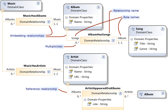
The following figure shows classes and relationships part of the DSL that is used as an example in this topic.
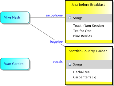
The next figure is an example model of this DSL:
Note
"Model" refers to an instance of your DSL that users create, and typically is displayed as a diagram. This topic discusses both the DSL Definition diagram and the model diagrams that appear when your DSL is used.
Defining Domain Classes
Domain Classes represent the concepts of your DSL. The instances are model elements. For example in a MusicLibrary DSL you might have Domain Classes named Album and Song.
To create a domain class, you can drag from the Named Domain Class tool to the diagram, and then rename the class.
For more information, see Properties of Domain Classes.
Create an Embedding Relationship for each Domain Class
Every domain class except the root class must be the target of at least one embedding relationship, or it must inherit from a class that is the target of an embedding relationship.
In a model, every model element is a node in a single tree of embedding relationships. The source and target of an embedding relationship are frequently referred to as parent and child.
The selection of a parent for a domain class depends on how you want its elements' lifetimes to depend on other elements. If a node of a tree is deleted, its sub-tree is usually deleted as well. Classes of element that have an independent existence are therefore embedded directly under the root class.
Typically, if you display an element inside another element, you want to indicate an owner relationship. In that case, the most appropriate parent class is the class of the container. The exception is when the item that you see inside a container is actually just a reference link to an independent element. In that case, deleting the container deletes the reference but not its target.
In the patterns of DSL definition described in this topic, we will assume that elements displayed inside a container will be deleted when the container is deleted. More complex schemes are possible, and can be achieved by defining rules.
| How element is displayed | Parent (embedding) class | Example in DSL Solution Template |
|---|---|---|
| Shape on diagram. Swimlane. |
Root class of DSL. | Minimal Language. Task Flow: Actor class. |
| Shape in swimlane. | Domain class of elements that are displayed as swimlanes. | Task Flow: Task class. |
| Item in list in shape, where item is deleted if container is deleted. Port on edge of shape. |
Domain class that is mapped to the container shape. | Class diagram: Attribute class. Component diagram: Port class. |
| Item in list, not deleted if container is deleted. | Root class of DSL. The list displays reference links. |
|
| Not directly displayed. | The class of which it forms part. |
In the Music Library example, Albums are displayed as rectangles in which the titles of Songs are listed. Therefore the parent of Album is the root class Music, and the parent of Song is Album.
To create a domain class and its embedding at the same time, click the Embedding Relationship tool, then click the parent class, and then click on a blank part of the diagram.
It is not usually necessary to adjust the name of the embedding relationship and its roles, because they will track the class names automatically.
For more information, see Properties of Domain Relationships and Properties of Domain Roles.
Note
Embedding is not the same as inheritance. Children in an embedding relationship do not inherit features from their parents.
Add Domain Properties to each Domain Class
Domain properties store values. Examples are: Name, Title, Publication Date.
Click Domain Properties in the class, press the ENTER key, and then type the name of a property. The default type of a domain property is String. If you want to change the type, select the domain property, and set the Type in the Properties window. If the type that you want is not in the drop-down list, see Adding Property Types.
Set an Element Name property. Select a domain property that can be used to identify elements in the language explorer. For example, in the Song domain class that you could select the Title domain property. In the Properties window, set Is Element Name to true.
Create Derived Domain Classes
If you want a domain class to have variants that inherit its properties and relationships, create classes that derive from it. For example, Album might have derived classes WMA and MP3.
Create the derived class using the Domain Class tool.
Click the Inheritance tool, click the derived class, and then click the base class.
Consider setting the Inheritance Modifier of the base class to abstract. If you think that you might need instances of the base class, consider instead creating a separate derived class for them.
Derived classes inherit the properties and roles of their base classes.
Tidy the DSL Definition Diagram
When you add relationships, some of your classes will appear in more than one place. To reduce the number of appearances and make the diagram wider, right-click the target class of a relationship, and then click Bring Tree Here. For the opposite effect, right-click the target class of a relationship and click Split Tree. If you do not see these menu commands, make sure that only the domain class is selected.
Use CTRL+Up and CTRL+Down to move domain classes and shape classes.
Test the domain classes
To test the new Domain Classes
Click Transform All Templates in the toolbar of Solution Explorer, to generate the DSL designer code. You can automate this step. For more information, see How to Automate Transform All Templates.
Build and run the DSL. Press F5 or CTRL+F5 to run a new instance of Visual Studio in experimental mode. In the experimental instance of Visual Studio, open or create a file that has the file name extension of your DSL.
Open the Explorer. At the side of the diagram is the language explorer window, which is usually named YourLanguage Explorer. If you do not see this window, it might be on a tab underneath Solution Explorer. If you cannot find it, on the View menu, point to Other Windows, and then click YourLanguage Explorer.
Your explorer presents a tree view of the model.
Create new elements. Right-click the root node at the top, and then click Add NewYourClass.
A new instance of your class appears in your language Explorer.
Verify that each instance has a different name when you create new instances. This will occur only if you have set the Is Element Name flag on a domain property.
Examine the domain properties. With an instance of your class selected, inspect the Properties window. It should show the domain properties that you defined on this domain class.
Save the file, close it, and re-open it. All the instances you created should be visible in the explorer, after you expand the nodes.
Defining Shapes on the Diagram
You can define classes of elements that appear on a diagram as rectangles, ellipses, or icons.
To define a class of elements that appear as shapes on a diagram
Define and test a domain class as described in Defining Domain Classes .
The parent of the class should be the root class. That is, there should be an embedding relationship between the root class and the new domain class.
If your diagram has swimlanes, the parent can be the domain class that is mapped to a swimlane. Before continuing with this procedure, see Defining a DSL that has Swimlanes.
Add a shape class to represent the elements on the model diagram. Drag from one of the following tools onto the DSL Definition diagram:
Geometry Shape provides a rectangle or ellipse.
Image Shape displays an image that you provide.
Compartment Shape is a rectangle that contains one or more lists of items.
Rename the shape class, which will appear on the right side of the DSL Definition diagram, under Shapes and Connectors.
Define an image, if you created an image shape.
Create an image file of any size. BMP, JPEG, GIF and EMF formats are supported.
In Solution Explorer, add the file to the solution under Dsl\Resources.
Return to the DSL Definition diagram and select the new image shape class.
In the Properties window, click the Image property.
In the Select Image dialog box, click the drop-down menu under File name, and select the image.
Add text decorators to the shape, to display the domain properties.
To display the name or title of the model element, you will probably need at least one text decorator.
Right-click the header of the shape class, point to Add, and then click Text Decorator. Set the name of the decorator, and in the Properties window set its Position.
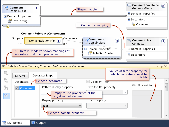
Connect each shape with a Diagram Element Map to the domain class that it should display.
Click the Diagram Element Map tool, then click the domain class, then click the shape class.
Map the properties to the text decorators.
Select the gray line between the domain class and the shape class that represents the diagram element map.
In the DSL Details window, click the Decorator Maps tab. If you do not see the DSL Details window, on the View menu, point to Other Windows and then click DSL Details. It is frequently necessary to raise the top of this window to see all its content.
Select the name of a decorator. Under Display property, select the name of a property of the domain class. Repeat this for each decorator.
If you want to display a property of a related element, click the drop-down tree navigator under Path to display property.
Make sure that a check mark appears alongside each decorator name.
Make a toolbox item for creating elements of the domain class.
In DSL Explorer, expand the Editor node and all its sub-nodes.
Right-click the node under Toolbox Tabs that has the same name as your DSL, for example MusicLibrary. Click Add Element Tool.
Note
If you right-click the Tools node, you will not see Add Element Tool. Instead, click the node above it.
In the Properties window with the new element tool selected, set Class to the domain class that you have recently added.
Set Caption and Tooltip.
Set Toolbox Icon to an icon that will appear in the toolbox. You can set it to a new icon or an icon already used for another tool.
To create a new icon, open Dsl\Resources in Solution Explorer. Copy and paste one of the existing element tool BMP files. Rename the pasted copy, and then double-click to edit it.
Return to the DSL Definition diagram, select the tool, and in the Properties window click [...] in Toolbox Icon. In the Select Bitmap dialog box, select your .BMP file from the drop-down menu.
For more information, see Properties of Geometry Shapes and Properties of Image Shapes.
To Test Shapes
Click Transform All Templates in the toolbar of Solution Explorer, to generate the DSL designer code.
Build and run the DSL. Press F5 or CTRL+F5 to run a new instance of Visual Studio in experimental mode. In the experimental instance of Visual Studio, open or create a file that has the file name extension of your DSL.
Verify that the element tools appear on the toolbox.
Create shapes by dragging from a tool onto the model diagram.
Verify that each text decorator appears, and that:
You can edit it, unless you have set the Is UI Read Only flag on the domain property.
When you edit the property either in the Properties window or in the decorator, the other view is updated.
After you first test a shape, you might want to adjust some its properties and add some more advanced features. For more information, see Customizing and Extending a Domain-Specific Language.
Defining Reference Relationships
You can define a reference relationship between any source domain class and any target domain class. Reference relationships are typically displayed on a diagram as connectors, which are lines between shapes.
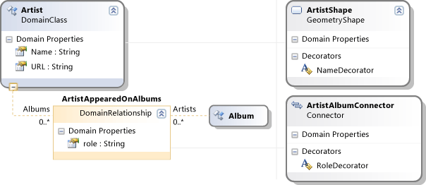
For example, if music Albums and Artists are displayed as shapes on your diagram, you could define a relationship named ArtistsAppearedOnAlbums that links Artists to the Albums on which they have worked. See the example in the figure.

Reference relationships can also link elements of the same type. For example, in a DSL representing a family tree, the relationship between parents and their children is a reference relationship from Person to Person.
Define a Reference Relationship
Click the Reference Relationship tool, then click the source domain class of the relationship, and then click the target domain class. The target class can be the same as the source class.
Each relationship has two roles, represented by the line at each side of the relationship box. You can select each role and set its properties in the Properties window.
Consider renaming the roles. For example, in a relationship between Person and Person, you might want to change the default names to Parents and Children, Manager and Subordinates, Teacher and Student, and so on.
Adjust the multiplicities of each role, if it is necessary. If you want each Person to have at most one Manager, set the multiplicity that appears below the Manager label on the diagram to 0..1.
Add domain properties to the relationship. In the figure, the Artist-Album relationship has a property of role.
Set the Allows Duplicates property of the relationship, if more than one link of the same class can exist between the same pair of model elements. For example, you could allow a Teacher to teach more than one Subject to the same Student.
For more information, see Properties of Domain Relationships and Properties of Domain Roles.
Define a Connector to Display the Relationship
A connector displays a line between two shapes on the model diagram.
Drag the Connector tool onto the DSL definition diagram.
Add text decorators if you want to display labels on the connector. Set their positions. To let the user move a text decorator, set its Is Moveable property.
Use the Diagram Element Map tool to link the connector to the reference relationship.
With the diagram element map selected, open the DSL Details window, and open the Decorator Maps tab.
Select each Decorator and set Display property to the correct domain property.
Make sure that a check mark appears next to each item in the Decorators list.
Define a Connection Builder Tool
In the DSL Explorer window, expand the Editor node and all its subnodes.
Right-click the node that has the same name as your DSL, and then click Add New Connection Tool.
While the new tool is selected, in the Properties window:
Set the Caption and Tooltip.
Click Connection Builder and select the appropriate builder for the new relationship.
Set Toolbox Icon to the icon that you want to appear in the toolbox. You can set it to a new icon or an icon already used for another tool.
To create a new icon, open Dsl\Resources in Solution Explorer. Copy and paste one of the existing element tool BMP files. Rename the pasted copy, and then double-click to edit it.
Return to the DSL Definition diagram, select the tool, and in the Properties window click [...] in Toolbox Icon. In the Select Bitmap dialog box, select your .BMP file from the drop-down menu.
To Test a Reference Relationship and Connector
Click Transform All Templates in the toolbar of Solution Explorer, to generate the DSL designer code.
Build and run the DSL. Press F5 or CTRL+F5 to run a new instance of Visual Studio in experimental mode. In the experimental instance of Visual Studio, open or create a file that has the file name extension of your DSL.
Verify that the connection tool appears on the toolbox.
Create shapes by dragging from a tool onto the model diagram.
Create connections between the shapes. Click the connector tool, click a shape, and then click another shape.
Verify that you cannot create connections between inappropriate classes. For example, if your relationship is between Albums and Artists, verify that you cannot link Artists to Artists.
Verify that the multiplicities are correct. For example, verify that you cannot connect a Person to more than one manager.
Verify that each text decorator appears, and that:
You can edit it, unless you have set the Is UI Read Only flag on the domain property.
When you edit the property either in the Properties window or in the decorator, the other view is updated.
After you first test a connector, you might want to adjust some its properties and add some more advanced features. For more information, see Customizing and Extending a Domain-Specific Language.
Defining Shapes that Contain Lists: Compartment Shapes
A compartment shape contains one or more lists of items. For example, in a Music Library DSL, you could use compartment shapes to represent music Albums. In each Album, there is a list of Songs.
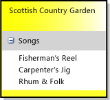
In the simplest method of achieving this effect in a DSL definition, you define one domain class for the container, and one domain class for each list. The container class is mapped to the compartment shape.
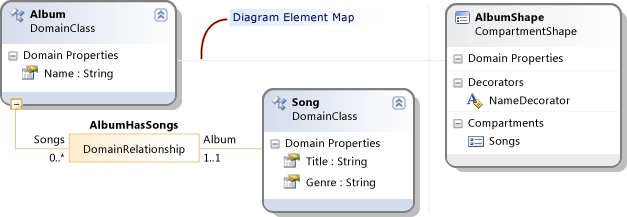
For more information, see Properties of Compartment Shapes.
To define a Compartment Shape
Create the container domain class. Click the Embedding Relationship tool, click the root class of the model, and then click a blank part of the DSL definition diagram. This creates the domain class that is named Album in the example figure.
Alternatively instead of embedding in the root class, you can embed the container in a domain class that is mapped to a swimlane.
Add a domain property such as Name to the class, and set its Is Element Name flag in the Properties window.
Create the list item domain class. Click the Embedding Relationship tool, click the container class (Album) and then click a blank part of the diagram. This creates the domain class that is named Song in the example figure.
Add a domain property such as Title to the class, and set its Is Element Name flag.
Add other domain properties.
Add another list item domain class for each list that you want to display.
To mix several types of item in the list, create classes that inherit from the list class. Make the list class abstract by setting its Inheritance Modifier.
For example, if you want classical music to be sorted by composer instead of artist, you could create two subclasses of Song, ClassicalSong and NonClassicalSong.
Create the compartment shape. Drag from the Compartment Shape tool onto the DSL definition diagram.
Add a text decorator and set its name.
Add a compartment and set its name.
To let the user hide the list compartments, right-click the compartment shape class, point to Add, and then click Expand/Collapse Decorator. In the Properties window, set the position of the decorator.
Click the Diagram Element Map tool, click the container domain class, and then click the compartment shape.
Select the diagram element map link between the domain class and the shape. In the DSL Details window:
Click the Decorators tab. Click the name of the decorator and then select the appropriate item under Display Property. Make sure that a check mark appears next to the name of the decorator.
Click the Compartment Maps tab.
Click the name of the compartment.
Under Displayed elements collection path, navigate to the list element class (Song). Click the drop-down arrow to use the navigator tool.
Under Display Property, select the property that should be displayed in the list. In the example, this is Title.
Note
By using the Path fields in the Decorator Map and Compartment map fields, you can make more complex relationships between the domain classes and the compartment shape.
To define a tool for creating the shape
Make a toolbox item for creating elements of the domain class.
In DSL Explorer, expand the Editor node and all its sub-nodes.
Right-click the node under Toolbox Tabs that has the same name as your DSL, for example MusicLibrary. Click Add Element Tool.
Note
If you right-click the Tools node, you will not see Add Element Tool. Instead, click the node above it.
In the Properties window with the new element tool selected, set Class to the domain class that you have recently added.
Set Caption and Tooltip.
Set Toolbox Icon to an icon that will appear in the toolbox. You can set it to a new icon or an icon already used for another tool.
To create a new icon, open Dsl\Resources in Solution Explorer. Copy and paste one of the existing element tool .BMP files. Rename the pasted copy, and then double-click to edit it.
Return to the DSL Definition diagram, select the tool, and in the Properties window click [...] in Toolbox Icon. In the Select Bitmap dialog box, select your BMP file from the drop-down menu.
To test a compartment shape
Click Transform All Templates in the toolbar of Solution Explorer, to generate the DSL designer code.
Build and run the DSL. Press F5 or CTRL+F5 to run a new instance of Visual Studio in experimental mode. In the experimental instance of Visual Studio, open or create a file that has the file name extension of your DSL.
Verify that the tool appears on the toolbox.
Drag the tool onto the model diagram. A shape is created.
Verify that the name of the element appears and is set automatically to a default value.
Right-click the header of the new shape, and then click Add Your List Item. In the example, the command is Add Song.
Verify that an item appears in the list and that it has a new name.
Click one of the list items, and then examine the Properties window. You should see the properties of the list items.
Open the language Explorer. Verify that you can see the container nodes with the list item nodes inside.
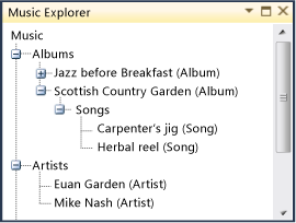
After you first test a compartment shape, you might want to adjust some of its properties and add some more advanced features. For more information, see Customizing and Extending a Domain-Specific Language.
Displaying a Reference Link in a Compartment
Usually, an element that you display in a compartment is a child of the element that is represented by the compartment shape. But sometimes, you would like to display an element that is linked to it with a reference relationship.
For example, we could add a second compartment to AlbumShape that displays a list of the Artists that are linked to the Album.
In this case, the compartment should display the link, instead of the referenced element. This is because when the user selects the item in the compartment and presses DELETE, you want the link to be deleted, not the referenced element.
Nevertheless, you can have the name of the referenced element appear in the compartment.
The following procedure assumes that you have already created the domain class, the reference relationship, the compartment shape, and the diagram element map, as described earlier in this section.
To display a reference link in a compartment
Add a compartment to the compartment shape. On the DSL Definition diagram, right-click the compartment shape class, point to Add, and then click Compartment.
Set Displayed elements collection path to navigate to the link, instead of its target element. Click the drop-down menu and use the tree view to select the reference relationship instead of its target. In the example, the relationship is ArtistAppearedOnAlbums.
Set Path to Display Property to navigate from the link to the target element. In the example, this is Artist.
Set Display Property to the appropriate property of the target element, for example Name.
Transform All Templates, build and run the DSL, and open a test model.
In the model diagram, create the appropriate classes of shape, set their names, and create a link between them. In the compartment shape, the names of linked elements should appear.
Select either the link or the item in the compartment shape. Both the link and the item should disappear.
Defining Ports on the Boundary of another Shape
A port is a shape that is located on the boundary of another shape.
Ports can also be used to provide a fixed connection point on another shape, to which the user can draw connectors. In this case, you can make the port shape transparent.
To see an example that uses ports, select the Component Diagram template when you create a new DSL solution. This example shows the main points that you can consider when you define ports:
There is a domain class that represents the container of the ports,
Component.There is a domain class that represents ports. In the example, this is
ComponentPort.There is an embedding relationship from the container domain class to the port domain class. For more information, see Defining Domain Classes.
If you want different types of port to be mixed on the same container, you can create subclasses of the port domain class. In the example,
InPortandOutPortinherit fromComponentPort.The container domain class can be mapped to any kind of shape. In the example, it is
ComponentShape. For more information, see Defining Shapes.The port domain classes are mapped to port shapes. You can either map the derived classes to separate port shape classes, or map the base class to one port shape class.
In other respects, port shapes behave as described in Defining Shapes.
For more information, see Properties of Port Shapes.
Defining a DSL that has Swimlanes
Swimlanes are a horizontal or vertical partition of a diagram. Each swimlane corresponds to a model element. Your DSL definition requires one domain class for the swimlane elements.
The best way to create a DSL with swimlanes is to create a new DSL solution and choose the Task Flow solution template. In the DSL Definition, the Actor class is the domain class mapped to the swimlane. Rename this and the other classes to suit your project.
To add a class that will be displayed as a shape inside a swimlane, create an Embedding Relationship between the swimlane class and your new class. Users will be able to drag elements from one swimlane to another, but each element will always be inside a particular swimlane. In the Task Flow solution template, FlowElement is a child of the swimlane class.
To add a class that will be displayed as a shape independently of swimlanes, create an Embedding Relationship between the root class and your new class. Users will be able to place these shapes anywhere on the diagram, including across the boundaries of swimlanes and outside the swimlanes. In the Task Flow solution template, Comment is a child of the root class.
For more information, see Properties of Swimlanes.
Adding Property Types
Domain Enumerations and Literals
A domain enumeration is a type with several literal values.
To add a domain enumeration, right-click the root of the model in the DSL Explorer and then click Add New Domain Enumeration. The element will appear in the DSL Explorer under the Domain Types node. This element does not appear on the diagram.
To add enumeration literals to the domain enumeration, right-click the domain enumeration in the DSL Explorer and then click Add New Enumeration Literal.
By default, a property that has an enumeration type can be set to only one value of the enumeration at a time. If you want users and programmers to be able to set any combination of values - a "bit field" - set the IsFlags property of the Enumeration.
External Types
When you set the type of a domain property, if you do not find the type you want in the Type drop-down list, you can add an external type. For example, you could add the System.Drawing.Color type to the list.
To add a type, right-click the root of the model in DSL Explorer, and then click Add New External Type. In the Properties window, set the name to Color and the namespace to System.Drawing. This type now appears in DSL Explorer under Domain Types. You can choose it whenever you set the type of a domain property.
Customizing the DSL
Using the techniques described in this topic, you can quickly create a DSL with a diagrammatic notation, a readable XML form, and the basic tools that are required to generate code and other artifacts.
There are two methods of extending the DSL definition:
Fine-tune the DSL by using more features of the DSL Definition. For example, you can make a single connector tool that can create several types of connector, and you can control the rules by which deleting one element also deletes related elements. These techniques are mostly achieved by setting values in the DSL Definition, and some require a few lines of program code.
For more information, see Customizing and Extending a Domain-Specific Language.
Extend your modeling tools by using program code to achieve more advanced effects. For example, you can create menu commands that can change the model, and you can create tools that integrate two or more DSLs. VMSDK is designed specifically to make it easy to integrate your extensions with the code that is generated from the DSL Definition. For more information, see Writing Code to Customize a Domain-Specific Language.
Changing the DSL Definition
When you create any item in a DSL definition, many default values are set automatically. After they have been set, you can change them. This simplifies the development of a DSL, while still allowing for powerful customizations.
For example, when you map a shape to an element, the Parent Element Path of the mapping is automatically set according to the embedding relationship of the domain class. However, if you later change the embedding relationship, the parent element path is not changed automatically.
You should therefore be aware that when you change some relationships in your DSL Definition, it is not unusual for errors to be reported either when you save the definition, or when you Transform All Templates. Most of these errors are easy to fix. Double-click the error report to see the location of the error.
See also How to: Change the Namespace of a Domain-Specific Language.
Troubleshooting
The following table lists some of the most common problems that are encountered when you design a DSL, together with suggestions for their solution. More advice is available on the Visualization Tools Extensibility Forum.
| Problem | Suggestion |
|---|---|
| The changes I have made in the DSL Definition file have no effect. | Click Transform All Templates in the toolbar above Solution Explorer, and then rebuild the solution. |
| Shapes show the name of a decorator instead of the property value. | Set up the decorator mapping. On the DSL Definition diagram, click the diagram element map, which is the gray line between the domain class and the shape class. Open the DSL Details window. If you cannot see it, on the View menu, point to Other Windows, and then click DSL Details. Click the Decorator Maps tab. Select the name of the decorator. Make sure that the box next to it is checked. Under Display property, select the name of a domain property. For more information, see Shapes on the Diagram. |
| In DSL Explorer, I cannot add to a collection. For example, when I right-click Tools, there is no "Add Tool" command in the menu. In the explorer for my DSL, I cannot add an element to a list. |
Right-click the item above the node that you are trying. When you want to add to a list, the Add command is not in the list node, but in its owner. |
| I created a domain class, but I can't create instances in the language explorer. | Every domain class except the root must be the target of an embedding relationship. |
| In the explorer for my DSL, elements are shown only with their type names. | In the DSL Definition, select a domain property of the class and in the Properties window, set Is Element Name to true. |
| My DSL always opens in the XML editor. | This can happen because of an error while the file was being read. However, even after you fix that error, you must explicitly reset the editor to be your DSL designer. Right-click the project item, click Open With and select YourLanguageDesigner (Default). |
| The toolbox of my DSL does not appear after I changed the assembly names. | Inspect and update DslPackage\GeneratedCode\Package.tt For more information, see How to: Change the Namespace of a Domain-Specific Language. |
| The toolbox of my DSL does not appear, but I have not changed the assembly name. Or, a message box appears reporting the failure to load an extension. |
Reset the experimental instance, and rebuild your solution. 1. At the Windows Start menu, under All Programs, expand Visual Studio SDK , then Tools, and then click Reset the Microsoft Visual Studio Experimental Instance. 2. On the Build menu, click Rebuild Solution. |