SDLC – Software Development Lifecycle … analyzing the battle ahead (part 6 of many)
Continued from SDLC – Software Development Lifecycle … is prototyping part of the good, the bad and/or the evil? (part 5 of many)
Overview
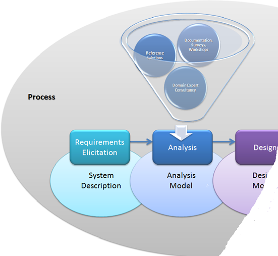
In recent posts we spoke about requirements elicitation (i.e. interviews), processes, models (i.e. agile) and will briefly touch on the next step which is concerned with analyzing the requirements and the system description. The Analysis phase receives input from a number of sources such as reference (existing) solutions, documentation, surveys, workshops, discussions and input from relevant domain experts and consultants. There are two main types of analysis, one the structured analysis, and the other the object oriented analysis, whereby there is a definite blur occurring between the two styles in projects I am involved in and with new age processes and methodologies.
Deliverable Chunks
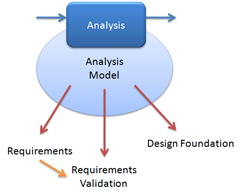
The analysis phase allows us to elaborate on the system description defined in previous phase(s) and allows us to create a solid foundation for the subsequent design phase.
What is important is to focus on the definition of the requirements validation requirements, which define and will allow us to verify the quality and functionality of the solution throughout the remainder of the solution.
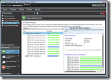 This, for example, is where I believe that Visual Studio 2010 “Camano” will deliver immense value, allowing us to define test cases early on during the lifetime of a solution and use these to assess and validate the quality of the solution from the beginning and throughout the solution lifetime.
There are numerous publications focused on analysis, the steps, the magic potions and the structured, formal and agile processes … I would much rather list some of the analysis model artefacts, so that we can decide, whether Visual Studio Team System fills parts of all of the important gaps.
 Some of the main deliverables include:
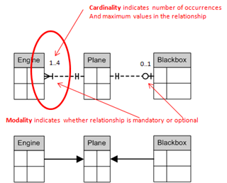
- Data Models, i.e. entity relationship diagram … which introduce exotic features such as cardinality, crow’s feet, modality, data objects, entities and much, much more. The diagram below shows cardinality, modality and two ways of representing the relationship between entities … the top one is using “crow’s feet notation”.
- Use Cases … which define the interaction between actors, also known as producers and consumers of information.
- Use Case Diagram … which defines a graphical representation of one or more actors and use cases.
- Universal Modelling Language (UML ) Diagrams, whereby we are only listing some of the models.
- Activity diagram, which shows the actions and decisions made as a specific function is processed.
- State diagram, which shows how the system reacts to events.
- Class diagram, which can highlight more fascinating terms such as aggregation, multiplicity and dependencies. Refer to the OO Model quick reference poster for some diagrams and explanations.
- Sequence diagram, which describes the behaviour of a system showing how classes move from state to state.
- Data Flow Diagram (DFD) … which highlights the primary input and output sources and the flow of data.
- Class Responsibility Collaborator (CRC) Model … which is an index card system, representing classes, showing collaborators, names and responsibilities.
- … and many, many, “many” more …
So what about Visual Studio Team System (VSTS) and Team Foundation Server (TFS)
 If we are talking about VSTS 2005/2008 we have a fairly comprehensive support for project|team management in the form of work items and Office Integration, but when it comes to analysis and design support, especially when referring to VSTS Architect Edition, it is time to shout “helmets on”.
With the introduction of a completely overhauled architecture sandbox in VSTS 2010, the age of analysis and design has arrived for VSTS|TFS users. Give the Community Technology Preview (CTP) for VSTS 2010 a visit and explore the new and comprehensive modelling and integration support. It is definitely safe to take off our helmets again, when perusing the 2010 CTP2 or later.
My previous posts Rosario 2010 CTP2 Agile Planning, Design, Reviewing a Solution and A close encounter with Sequence Diagram should also give you the warm fuzzy feeling and an idea of what is coming.
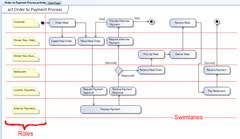
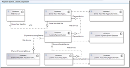
Here are a few exciting snapshots of of the blog posts, which show the long awaited sign of state of the art modelling tools.
With the analysis complete, we need to focus on battle design. Guess that will be part 6 of many :)
Comments
Anonymous
February 21, 2009
This post is simply a collection of the various posts that made up the “ SDLC – Software DevelopmentAnonymous
February 24, 2009
The comment has been removedAnonymous
February 26, 2009
Continued from SDLC – Software Development Lifecycle … analyzing the battle ahead (part 6 of many) .Anonymous
May 19, 2015
I am in an SDLC class we were told to use VISIO. As a student I can not afford it. Are their other choices to use for drawing and modeling?Anonymous
May 19, 2015
@John, if you are a student you can explore www.dreamspark.com/.../Subscription.aspx. If your academic institution has the premium subscription, Visio is included. Alternatively you can explore the web for alternatives.

![image_thumb3[1] image_thumb3[1]](https://msdntnarchive.z22.web.core.windows.net/media/TNBlogsFS/BlogFileStorage/blogs_msdn/willy-peter_schaub/WindowsLiveWriter/SDLCSoftwareDevelopmentLifecycle_EB81/image_thumb3%5B1%5D_5511e6b5-45e8-4ee9-a395-3212579a195b.png)
