Asignaciones de pin de Raspberry Pi 2 y 3
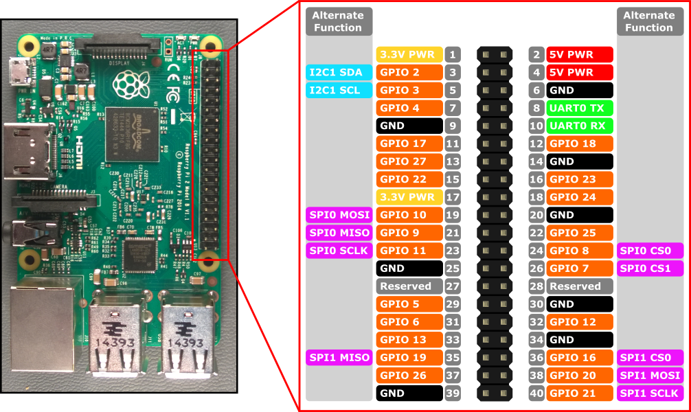
Las interfaces de hardware para Raspberry Pi 2 y Raspberry Pi 3 se exponen a través del encabezado de 40 patillas J8 en la placa. Entre las funcionalidades se incluyen:
- 24x : patillas GPIO
- 1x - UART serie (RPi3 solo incluye mini UART)
- 2x : bus SPI
- 1x - Bus I2C
- 2x - 5V pines de alimentación
- 2x : clavijas de alimentación de 3,3V
- 8x - Patillas de suelo
Patillas GPIO
Echemos un vistazo al GPIO disponible en este dispositivo.
Información general sobre patillas GPIO
Se puede acceder a los siguientes patillas GPIO a través de las API:
GPIO# Extracción de encendido Funciones alternativas Pin de encabezado 2 PullUp I2C1 SDA 3 3 PullUp I2C1 SCL 5 4 PullUp 7 5 PullUp 29 6 PullUp 31 7 PullUp SPI0 CS1 26 8 PullUp SPI0 CS0 24 9 Desplegable SPI0 MISO 21 10 Desplegable SPI0 MOSI 19 11 Desplegable SPI0 SCLK 23 12 Desplegable 32 13 Desplegable 33 16 Desplegable SPI1 CS0 36 17 Desplegable 11 18 Desplegable 12 19 Desplegable SPI1 MISO 35 20 Desplegable SPI1 MOSI 38 21 Desplegable SPI1 SCLK 40 22 Desplegable 15 23 Desplegable 16 24 Desplegable 18 25 Desplegable 22 26 Desplegable 37 27 Desplegable 13 35* PullUp LED de alimentación roja 47* PullUp LED de actividad verde
* = Raspberry Pi 2 ONLY. GPIO 35 y 47 no están disponibles en Raspberry Pi 3.
Ejemplo de GPIO
Por ejemplo, el código siguiente abre GPIO 5 como salida y escribe un "1" digital en la patilla:
using Windows.Devices.Gpio;

public void GPIO()
{
    // Get the default GPIO controller on the system
    GpioController gpio = GpioController.GetDefault();
    if (gpio == null)
        return; // GPIO not available on this system

    // Open GPIO 5
    using (GpioPin pin = gpio.OpenPin(5))
    {
        // Latch HIGH value first. This ensures a default value when the pin is set as output
        pin.Write(GpioPinValue.High);

        // Set the IO direction as output
        pin.SetDriveMode(GpioPinDriveMode.Output);

    } // Close pin - will revert to its power-on state
}
Al abrir un pin, estará en su estado de encendido, lo que puede incluir una resistencia de extracción. Para desconectar las resistencias de extracción y obtener una entrada de alta impedancia, establezca el modo de unidad en GpioPinDriveMode.Input:
pin.SetDriveMode(GpioPinDriveMode.Input);
Cuando se cierra un pin, se revierte a su estado de encendido.
Muxación de patillas
Algunos patillas GPIO pueden realizar varias funciones. De forma predeterminada, los patillas se configuran como entradas GPIO. Cuando se abre una función alternativa mediante una llamada a I2cDevice.FromIdAsync() o SpiDevice.FromIdAsync() , las patillas requeridas por la función se cambian automáticamente ("muxed") a la función correcta. Cuando el dispositivo se cierra llamando a I2cDevice.Dispose() o SpiDevice.Dispose(), las patillas vuelven a su función predeterminada. Si intenta usar un pin para dos funciones diferentes a la vez, se producirá una excepción al intentar abrir la función en conflicto. Por ejemplo,
var controller = GpioController.GetDefault();
var gpio2 = controller.OpenPin(2);      // open GPIO2, shared with I2C1 SDA

var dis = await DeviceInformation.FindAllAsync(I2cDevice.GetDeviceSelector());
var i2cDevice = await I2cDevice.FromIdAsync(dis[0].Id, new I2cConnectionSettings(0x55)); // exception thrown because GPIO2 is open

gpio2.Dispose(); // close GPIO2
var i2cDevice = await I2cDevice.FromIdAsync(dis[0].Id, new I2cConnectionSettings(0x55)); // succeeds because gpio2 is now available

var gpio2 = controller.OpenPin(2); // throws exception because GPIO2 is in use as SDA1

i2cDevice.Dispose(); // release I2C device
var gpio2 = controller.OpenPin(2); // succeeds now that GPIO2 is available
UART serie
Hay un UART serie disponible en RPi2/3: UART0
- Pin 8 - UART0 TX
- Pin 10 - UART0 RX
En el ejemplo siguiente se inicializa UART0 y se realiza una escritura seguida de una lectura:
using Windows.Storage.Streams;
using Windows.Devices.Enumeration;
using Windows.Devices.SerialCommunication;

public async void Serial()
{
    string aqs = SerialDevice.GetDeviceSelector("UART0");                   /* Find the selector string for the serial device   */
    var dis = await DeviceInformation.FindAllAsync(aqs);                    /* Find the serial device with our selector string  */
    SerialDevice SerialPort = await SerialDevice.FromIdAsync(dis[0].Id);    /* Create an serial device with our selected device */

    /* Configure serial settings */
    SerialPort.WriteTimeout = TimeSpan.FromMilliseconds(1000);
    SerialPort.ReadTimeout = TimeSpan.FromMilliseconds(1000);
    SerialPort.BaudRate = 9600;                                             /* mini UART: only standard baud rates */
    SerialPort.Parity = SerialParity.None;                                  /* mini UART: no parities */
    SerialPort.StopBits = SerialStopBitCount.One;                           /* mini UART: 1 stop bit */
    SerialPort.DataBits = 8;

    /* Write a string out over serial */
    string txBuffer = "Hello Serial";
    DataWriter dataWriter = new DataWriter();
    dataWriter.WriteString(txBuffer);
    uint bytesWritten = await SerialPort.OutputStream.WriteAsync(dataWriter.DetachBuffer());

    /* Read data in from the serial port */
    const uint maxReadLength = 1024;
    DataReader dataReader = new DataReader(SerialPort.InputStream);
    uint bytesToRead = await dataReader.LoadAsync(maxReadLength);
    string rxBuffer = dataReader.ReadString(bytesToRead);
}
Ten en cuenta que debes agregar la siguiente funcionalidad al archivo Package.appxmanifest en tu proyecto de UWP para ejecutar código UART serie:
Visual Studio 2017 tiene un error conocido en el Diseñador de manifiestos (el editor visual para archivos appxmanifest) que afecta a la funcionalidad serialcommunication. Si appxmanifest agrega la funcionalidad serialcommunication, al modificar appxmanifest con el diseñador se dañará el appxmanifest (se perderá el elemento secundario Device xml). Puedes solucionar este problema editando manualmente appxmanifest haciendo clic con el botón derecho en tu appxmanifest y seleccionando Ver código en el menú contextual.
  <Capabilities>
    <DeviceCapability Name="serialcommunication">
      <Device Id="any">
        <Function Type="name:serialPort" />
      </Device>
    </DeviceCapability>
  </Capabilities>
Bus I2C
Echemos un vistazo al bus I2C disponible en este dispositivo.
Introducción a I2C
Hay un controlador I2C I2C1 expuesto en el encabezado de patilla con dos líneas SDA y SCL. 1.8KΩ los resistores internos de extracción ya están instalados en la placa para este bus.
Nombre de señal Número de patilla de encabezado Número de Gpio SDA 3 2 SCL 5 3
En el ejemplo siguiente se inicializa I2C1 y se escriben datos en un dispositivo I2C con dirección 0x40:
using Windows.Devices.Enumeration;
using Windows.Devices.I2c;

public async void I2C()
{
    // 0x40 is the I2C device address
    var settings = new I2cConnectionSettings(0x40);
    // FastMode = 400KHz
    settings.BusSpeed = I2cBusSpeed.FastMode;

    // Create an I2cDevice with the specified I2C settings
    var controller = await I2cController.GetDefaultAsync();

    using (I2cDevice device = controller.GetDevice(settings))
    {
        byte[] writeBuf = { 0x01, 0x02, 0x03, 0x04 };
        device.Write(writeBuf);
    }
}
Bus SPI
Hay dos controladores de bus SPI disponibles en el RPi2/3.
SPI0
Nombre de señal Número de patilla de encabezado Número de Gpio MOSI 19 10 MISO 21 9 SCLK 23 11 CS0 24 8 CS1 26 7
SPI1
Nombre de señal Número de patilla de encabezado Número de Gpio MOSI 38 20 MISO 35 19 SCLK 40 21 CS0 36 16
Ejemplo spi
A continuación se muestra un ejemplo de cómo realizar una escritura SPI en bus SPI0 mediante chip select 0:
using Windows.Devices.Enumeration;
using Windows.Devices.Spi;

public async void SPI()
{
    // Use chip select line CS0
    var settings = new SpiConnectionSettings(0);
    // Set clock to 10MHz
    settings.ClockFrequency = 10000000;

    // Get a selector string that will return our wanted SPI controller
    string aqs = SpiDevice.GetDeviceSelector("SPI0");

    // Find the SPI bus controller devices with our selector string
    var dis = await DeviceInformation.FindAllAsync(aqs);

    // Create an SpiDevice with our selected bus controller and Spi settings
    using (SpiDevice device = await SpiDevice.FromIdAsync(dis[0].Id, settings))
    {
        byte[] writeBuf = { 0x01, 0x02, 0x03, 0x04 };
        device.Write(writeBuf);
    }
}