Información general sobre geometría
En esta información general se describe cómo usar las clases Geometry de Windows Presentation Foundation (WPF) para describir formas. En este tema también se contrastan las diferencias entre los objetos Geometry y los elementos Shape.
¿Qué es una geometría?
La clase Geometry y las clases que derivan de ella, como EllipseGeometry, PathGeometry y CombinedGeometry, permiten describir la geometría de una forma 2D. Estas descripciones geométricas tiene muchos usos, como definir una forma para pintarla en la pantalla o definir regiones de recorte y pruebas de posicionamiento. Incluso se puede usar una geometría para definir un trazado de animación.
Los objetos Geometry pueden ser simples, como rectángulos y círculos, o compuestos, creados a partir de dos o más objetos geométricos. Se pueden crear geometrías más complejas mediante las clases PathGeometry y StreamGeometry, que permiten describir arcos y curvas.
Como Geometry es un tipo de Freezable, los objetos Geometry presentan características especiales: se pueden declarar como recursos, compartirse entre varios objetos, convertirse en objetos de solo lectura para mejorar el rendimiento, clonarse y hacerse seguros para subprocesos. Para obtener más información sobre las diferentes características que ofrecen los objetos Freezable, consulte Información general sobre objetos Freezable.
Geometrías frente a formas
Las clases Geometry y Shape parecen similares en que ambas describen formas 2D (compare EllipseGeometry y Ellipse, por ejemplo), pero hay diferencias importantes.
En primer lugar, la clase Geometry hereda de la clase Freezable, mientras que la clase Shape hereda de FrameworkElement. Dado que son elementos, los objetos Shape pueden representarse a sí mismos y participar en el sistema de diseño, mientras que los objetos Geometry no pueden.
Si bien los objetos Shape se pueden usar más rápidamente que los objetos Geometry, los objetos Geometry son más versátiles. Mientras que un objeto Shape se usa para representar gráficos 2D, un objeto Geometry se puede usar para, por ejemplo, definir la región geométrica de gráficos 2D, definir una región de recorte o definir una región de prueba de posicionamiento.
La forma del trazado
Una Shape, la clase Path, usa realmente un objeto Geometry para describir su contenido. Si establece la propiedad Data de Path con Geometry y establece sus propiedades Fill y Stroke, puede representar un elemento Geometry.
Propiedades comunes que aceptan un objeto Geometry
En las secciones anteriores se menciona que se pueden usar objetos Geometry con otros objetos con diversos fines, como dibujar formas, crear animaciones y efectuar recortes. En la tabla siguiente se muestran varias clases que tienen propiedades que aceptan un objeto Geometry.
| Tipo | Propiedad |
|---|---|
| DoubleAnimationUsingPath | PathGeometry |
| DrawingGroup | ClipGeometry |
| GeometryDrawing | Geometry |
| Path | Data |
| UIElement | Clip |
Tipos de objeto Geometry simples
La clase base de todas las geometrías es la clase abstracta Geometry. Las clases que se derivan de la clase Geometry pueden agruparse aproximadamente en tres categorías: geometrías simples, geometrías de trazado y geometrías compuestas.
Las clases de geometría simple incluyen LineGeometry, RectangleGeometry y EllipseGeometry, y se usan para crear formas geométricas básicas, como líneas, rectángulos y círculos.
Un objeto LineGeometry se define especificando el punto inicial de la línea y el punto final.
Un objeto RectangleGeometry se define con una estructura Rect, que especifica su posición relativa y su ancho y altura. Puede crear un rectángulo redondeado estableciendo las propiedades RadiusX y RadiusY.
EllipseGeometry se define mediante un punto central, un radio X y un radio Y. En los ejemplos siguientes se muestra cómo crear geometrías simples de representación y recorte.
Estas mismas formas, así como otras formas más complejas, se pueden crear mediante un PathGeometry o combinando varios objetos geométricos, pero estas clases ofrecen una manera más sencilla de producir estas formas geométricas básicas.
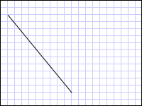
En el siguiente ejemplo se muestra cómo crear y representar una clase LineGeometry. Como se ha observado anteriormente, un objeto Geometry no puede dibujarse a sí mismo, por lo que el ejemplo usa una forma Path para representar la línea. Dado que una línea no tiene área, establecer la propiedad Fill de Path no tendría ningún efecto; en su lugar, solo se especifican las propiedades Stroke y StrokeThickness. En la siguiente ilustración se muestra el resultado del ejemplo.
 Un objeto LineGeometrygraphicsmm_line
Objeto LineGeometry dibujado desde (10,20) hasta (100,130)
<Path Stroke="Black" StrokeThickness="1" >
  <Path.Data>
    <LineGeometry StartPoint="10,20" EndPoint="100,130" />
  </Path.Data>
</Path>
LineGeometry myLineGeometry = new LineGeometry();
myLineGeometry.StartPoint = new Point(10,20);
myLineGeometry.EndPoint = new Point(100,130);

Path myPath = new Path();
myPath.Stroke = Brushes.Black;
myPath.StrokeThickness = 1;
myPath.Data = myLineGeometry;
Dim myLineGeometry As New LineGeometry()
myLineGeometry.StartPoint = New Point(10,20)
myLineGeometry.EndPoint = New Point(100,130)

Dim myPath As New Path()
myPath.Stroke = Brushes.Black
myPath.StrokeThickness = 1
myPath.Data = myLineGeometry
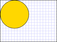
En el siguiente ejemplo se muestra cómo crear y representar un objeto EllipseGeometry. En el ejemplo se establece Center de EllipseGeometry en el punto 50,50, y el radio X y el radio Y se establecen en 50, lo que crea un círculo con un diámetro de 100. El interior de la elipse se pinta asignando un valor a la propiedad de relleno del elemento de trazado, en este caso, Gold. En la siguiente ilustración se muestra el resultado del ejemplo.
 Un objeto EllipseGeometrygraphicsmm_ellipse
Objeto EllipseGeometry dibujado en (50,50)
<Path Fill="Gold" Stroke="Black" StrokeThickness="1">
  <Path.Data>
    <EllipseGeometry Center="50,50" RadiusX="50" RadiusY="50" />
  </Path.Data>
</Path>
EllipseGeometry myEllipseGeometry = new EllipseGeometry();
myEllipseGeometry.Center = new Point(50, 50);
myEllipseGeometry.RadiusX = 50;
myEllipseGeometry.RadiusY = 50;

Path myPath = new Path();
myPath.Fill = Brushes.Gold;
myPath.Stroke = Brushes.Black;
myPath.StrokeThickness = 1;
myPath.Data = myEllipseGeometry;
Dim myEllipseGeometry As New EllipseGeometry()
myEllipseGeometry.Center = New Point(50, 50)
myEllipseGeometry.RadiusX = 50
myEllipseGeometry.RadiusY = 50

Dim myPath As New Path()
myPath.Fill = Brushes.Gold
myPath.Stroke = Brushes.Black
myPath.StrokeThickness = 1
myPath.Data = myEllipseGeometry
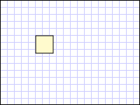
En el siguiente ejemplo se muestra cómo crear y representar una clase LineGeometry. La posición y las dimensiones del rectángulo se definen mediante una estructura Rect. La posición es 50,50 y el alto y ancho son ambos 25, lo que crea un cuadrado. En la siguiente ilustración se muestra el resultado del ejemplo.
 RectangleGeometrygraphicsmm_rectangle
Objeto RectangleGeometry dibujado en 50,50
<Path Fill="LemonChiffon" Stroke="Black" StrokeThickness="1">
  <Path.Data>
    <RectangleGeometry Rect="50,50,25,25" />
  </Path.Data>
</Path>
RectangleGeometry myRectangleGeometry = new RectangleGeometry();
myRectangleGeometry.Rect = new Rect(50,50,25,25);

Path myPath = new Path();
myPath.Fill = Brushes.LemonChiffon;
myPath.Stroke = Brushes.Black;
myPath.StrokeThickness = 1;
myPath.Data = myRectangleGeometry;
Dim myRectangleGeometry As New RectangleGeometry()
myRectangleGeometry.Rect = New Rect(50,50,25,25)

Dim myPath As New Path()
myPath.Fill = Brushes.LemonChiffon
myPath.Stroke = Brushes.Black
myPath.StrokeThickness = 1
myPath.Data = myRectangleGeometry
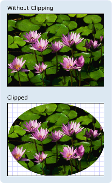
En el siguiente ejemplo se muestra cómo usar un objeto EllipseGeometry como región de recorte de una imagen. Un objeto Image se define con un valor Width de 200 y un valor Height de 150. Un objeto EllipseGeometry con un valor RadiusX de 100, un valor RadiusY de 75 y un valor Center de 100,75 se establece en la propiedad Clip de la imagen. Solo se mostrará la parte de la imagen que queda dentro del área de la elipse. En la siguiente ilustración se muestra el resultado del ejemplo.
 Una imagen con o sin recortegraphicsmm_clipexample
Objeto EllipseGeometry usado para recortar un control Image
<Image
  Source="sampleImages\Waterlilies.jpg"
  Width="200" Height="150" HorizontalAlignment="Left">
  <Image.Clip>
    <EllipseGeometry
      RadiusX="100"
      RadiusY="75"
      Center="100,75"/>
  </Image.Clip>
</Image>
// Create the image to clip.
Image myImage = new Image();
Uri imageUri =
    new Uri(@"C:\\Documents and Settings\\All Users\\Documents\My Pictures\\Sample Pictures\\Water lilies.jpg", UriKind.Relative);
myImage.Source = new BitmapImage(imageUri);
myImage.Width = 200;
myImage.Height = 150;
myImage.HorizontalAlignment = HorizontalAlignment.Left;

// Use an EllipseGeometry to define the clip region.
EllipseGeometry myEllipseGeometry = new EllipseGeometry();
myEllipseGeometry.Center = new Point(100, 75);
myEllipseGeometry.RadiusX = 100;
myEllipseGeometry.RadiusY = 75;
myImage.Clip = myEllipseGeometry;
' Create the image to clip.
Dim myImage As New Image()
Dim imageUri As New Uri("C:\\Documents and Settings\\All Users\\Documents\My Pictures\\Sample Pictures\\Water lilies.jpg", UriKind.Relative)
myImage.Source = New BitmapImage(imageUri)
myImage.Width = 200
myImage.Height = 150
myImage.HorizontalAlignment = HorizontalAlignment.Left

' Use an EllipseGeometry to define the clip region.
Dim myEllipseGeometry As New EllipseGeometry()
myEllipseGeometry.Center = New Point(100, 75)
myEllipseGeometry.RadiusX = 100
myEllipseGeometry.RadiusY = 75
myImage.Clip = myEllipseGeometry
Geometrías de trazado
La clase PathGeometry y su equivalente ligero, la clase StreamGeometry, ofrecen los medios para describir varias figuras complejas compuestas por arcos, curvas y líneas.
En el corazón de un elemento PathGeometry hay una colección de objetos PathFigure, denominados así porque cada figura describe una forma discreta en PathGeometry. Cada PathFigure está compuesto de uno o más objetos PathSegment, cada uno de los cuales describe un segmento de la figura.
Hay muchos tipos de segmentos.
| Tipo de segmento | Descripción | Ejemplo |
|---|---|---|
| ArcSegment | Crea un arco elíptico entre dos puntos. | Crear un arco elíptico. |
| BezierSegment | Crea una curva Bézier cúbica entre dos puntos. | Crear una curva Bézier cúbica. |
| LineSegment | Crea una línea entre dos puntos. | Crear un LineSegment en una clase PathGeometry |
| PolyBezierSegment | Crea una serie de curvas Bézier cúbicas. | Consulte la página del tipo PolyBezierSegment. |
| PolyLineSegment | Crea una serie de líneas. | Consulte la página del tipo PolyBezierSegment. |
| PolyQuadraticBezierSegment | Crea una serie de curvas Bézier cuadráticas. | Consulte la página PolyQuadraticBezierSegment. |
| QuadraticBezierSegment | Crea una curva Bézier cuadrática. | Crear una curva Bézier cuadrática. |
Los segmentos comprendidos en un objeto PathFigure se combinan en una sola forma geométrica donde el punto final de cada segmento es el punto inicial del siguiente segmento. La propiedad StartPoint de un objeto PathFigure especifica el punto desde el que se dibuja el primer segmento. Cada segmento posterior comienza en el punto final del segmento anterior. Por ejemplo, se puede definir una línea vertical de 10,50 a 10,150 estableciendo la propiedad StartPoint en 10,50 y creando un objeto LineSegment con un valor de propiedad Point de 10,150.
En el ejemplo siguiente se crea un objeto PathGeometry simple compuesto de un único PathFigure con un objeto LineSegment y se muestra mediante un elemento Path. El elemento StartPoint del objeto PathFigure se establece en 10,20 y LineSegment se define con un punto final de 100,130. En la ilustración siguiente se muestra el objeto PathGeometry que se ha creado en este ejemplo.
 Un objeto LineGeometrygraphicsmm_line
Objeto PathGeometry que contiene un solo LineSegment
<Path Stroke="Black" StrokeThickness="1">
  <Path.Data>
    <PathGeometry>
      <PathGeometry.Figures>
        <PathFigure StartPoint="10,20">
          <PathFigure.Segments>
            <LineSegment Point="100,130"/>
          </PathFigure.Segments>
        </PathFigure>
      </PathGeometry.Figures>
    </PathGeometry>
  </Path.Data>
</Path>
// Create a figure that describes a
// line from (10,20) to (100,130).
PathFigure myPathFigure = new PathFigure();
myPathFigure.StartPoint = new Point(10,20);
myPathFigure.Segments.Add(
    new LineSegment(new Point(100,130),
    true /* IsStroked */ ));

/// Create a PathGeometry to contain the figure.
PathGeometry myPathGeometry = new PathGeometry();
myPathGeometry.Figures.Add(myPathFigure);

// Display the PathGeometry.
Path myPath = new Path();
myPath.Stroke = Brushes.Black;
myPath.StrokeThickness = 1;
myPath.Data = myPathGeometry;
' Create a figure that describes a
' line from (10,20) to (100,130).
Dim myPathFigure As New PathFigure()
myPathFigure.StartPoint = New Point(10,20)
myPathFigure.Segments.Add(New LineSegment(New Point(100,130), True)) ' IsStroked

''' Create a PathGeometry to contain the figure.
Dim myPathGeometry As New PathGeometry()
myPathGeometry.Figures.Add(myPathFigure)

' Display the PathGeometry.
Dim myPath As New Path()
myPath.Stroke = Brushes.Black
myPath.StrokeThickness = 1
myPath.Data = myPathGeometry
Vale la pena comparar este ejemplo con el ejemplo de LineGeometry anterior. La sintaxis que se usa para PathGeometry es mucho más detallada que la que se usa para un objeto LineGeometry simple, y puede que tenga más sentido usar la clase LineGeometry en este caso, pero la sintaxis detallada de PathGeometry permite crear regiones geométricas extremadamente complejas.
Se pueden crear geometrías más complejas mediante una combinación de objetos PathSegment.
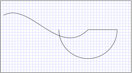
En el ejemplo siguiente se usa BezierSegment, un objeto LineSegment, y un objeto ArcSegment para crear una forma. En primer lugar, se crea una curva Bézier cúbica definiendo cuatro puntos: un punto inicial, que es el punto final del segmento anterior, un punto final (Point3) y dos puntos de control (Point1 y Point2). Los dos puntos de control de una curva Bézier cúbica se comportan como imanes, atraen hacia ellos partes de lo que de otra manera sería una línea recta y generan una curva. El primer punto de control, Point1, afecta la parte inicial de la curva; el segundo punto de control, Point2, afecta la parte final de la curva.
A continuación, se agrega un objeto LineSegment, que se dibuja entre el punto final del BezierSegment anterior que lo precedía en el punto especificado por su propiedad LineSegment.
A continuación, se agrega un objeto ArcSegment, que se dibuja entre el punto final del LineSegment anterior en el punto especificado por su propiedad Point. En el ejemplo también se especifica el radio X e Y del arco (Size), un ángulo de rotación (RotationAngle), una marca que indica el tamaño que debería tener el ángulo del arco resultante (IsLargeArc) y un valor que indica en qué dirección se dibuja el arco (SweepDirection). En la ilustración siguiente se muestra cómo se representa este ejemplo.
 Un objeto PathGeometry con un arcographicsmm_path2
PathGeometry
<Path Stroke="Black" StrokeThickness="1" >
  <Path.Data>
    <PathGeometry>
      <PathGeometry.Figures>
        <PathFigure StartPoint="10,50">
          <PathFigure.Segments>
            <BezierSegment
              Point1="100,0"
              Point2="200,200"
              Point3="300,100"/>
            <LineSegment Point="400,100" />
            <ArcSegment
              Size="50,50" RotationAngle="45"
              IsLargeArc="True" SweepDirection="Clockwise"
              Point="200,100"/>
          </PathFigure.Segments>
        </PathFigure>
      </PathGeometry.Figures>
    </PathGeometry>
  </Path.Data>
</Path>
// Create a figure.
PathFigure myPathFigure = new PathFigure();
myPathFigure.StartPoint = new Point(10,50);
myPathFigure.Segments.Add(
    new BezierSegment(
        new Point(100,0),
        new Point(200,200),
        new Point(300,100),
        true /* IsStroked */  ));
myPathFigure.Segments.Add(
    new LineSegment(
        new Point(400,100),
        true /* IsStroked */ ));
myPathFigure.Segments.Add(
    new ArcSegment(
        new Point(200,100),
        new Size(50,50),
        45,
        true, /* IsLargeArc */
        SweepDirection.Clockwise,
        true /* IsStroked */ ));

/// Create a PathGeometry to contain the figure.
PathGeometry myPathGeometry = new PathGeometry();
myPathGeometry.Figures.Add(myPathFigure);

// Display the PathGeometry.
Path myPath = new Path();
myPath.Stroke = Brushes.Black;
myPath.StrokeThickness = 1;
myPath.Data = myPathGeometry;
' Create a figure.
Dim myPathFigure As New PathFigure()
myPathFigure.StartPoint = New Point(10,50)
myPathFigure.Segments.Add(New BezierSegment(New Point(100,0), New Point(200,200), New Point(300,100), True)) ' IsStroked
myPathFigure.Segments.Add(New LineSegment(New Point(400,100), True)) ' IsStroked
myPathFigure.Segments.Add(New ArcSegment(New Point(200,100), New Size(50,50), 45, True, SweepDirection.Clockwise, True)) ' IsStroked  -  IsLargeArc

''' Create a PathGeometry to contain the figure.
Dim myPathGeometry As New PathGeometry()
myPathGeometry.Figures.Add(myPathFigure)

' Display the PathGeometry.
Dim myPath As New Path()
myPath.Stroke = Brushes.Black
myPath.StrokeThickness = 1
myPath.Data = myPathGeometry
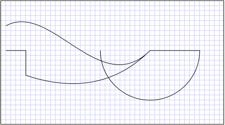
Se pueden crear geometrías todavía más complejas mediante el uso de varios objetos PathFigure en un elemento PathGeometry.
En el ejemplo siguiente se crea un elemento PathGeometry con dos objetos PathFigure, cada uno de los cuales contiene varios objetos PathSegment. Se utilizan el elemento PathFigure del ejemplo anterior y un elemento PathFigure con un objeto PolyLineSegment y un objeto QuadraticBezierSegment. Un objeto PolyLineSegment se define con una matriz de puntos y QuadraticBezierSegment se define con un punto de control y un punto final. En la ilustración siguiente se muestra cómo se representa este ejemplo.
 Un objeto PathGeometry con un arco que incluye dos objetos PathFigure.graphicsmm_path
Objeto PathGeometry con varias figuras
<Path Stroke="Black" StrokeThickness="1" >
  <Path.Data>
    <PathGeometry>
      <PathGeometry.Figures>
        <PathFigure StartPoint="10,50">
          <PathFigure.Segments>
            <BezierSegment
              Point1="100,0"
              Point2="200,200"
              Point3="300,100"/>
            <LineSegment Point="400,100" />
            <ArcSegment
              Size="50,50" RotationAngle="45"
              IsLargeArc="True" SweepDirection="Clockwise"
              Point="200,100"/>
          </PathFigure.Segments>
        </PathFigure>

        <PathFigure StartPoint="10,100">
          <PathFigure.Segments>
            <PolyLineSegment Points="50,100 50,150" />
            <QuadraticBezierSegment Point1="200,200" Point2="300,100"/>
          </PathFigure.Segments>
        </PathFigure>
      </PathGeometry.Figures>
    </PathGeometry>
  </Path.Data>
</Path>
PathGeometry myPathGeometry = new PathGeometry();

// Create a figure.
PathFigure pathFigure1 = new PathFigure();
pathFigure1.StartPoint = new Point(10,50);
pathFigure1.Segments.Add(
    new BezierSegment(
        new Point(100,0),
        new Point(200,200),
        new Point(300,100),
        true /* IsStroked */ ));
pathFigure1.Segments.Add(
    new LineSegment(
        new Point(400,100),
        true /* IsStroked */ ));
pathFigure1.Segments.Add(
    new ArcSegment(
        new Point(200,100),
        new Size(50,50),
        45,
        true, /* IsLargeArc */
        SweepDirection.Clockwise,
        true /* IsStroked */ ));
myPathGeometry.Figures.Add(pathFigure1);

// Create another figure.
PathFigure pathFigure2 = new PathFigure();
pathFigure2.StartPoint = new Point(10,100);
Point[] polyLinePointArray =
    new Point[]{ new Point(50, 100), new Point(50, 150)};
PolyLineSegment myPolyLineSegment = new PolyLineSegment();
myPolyLineSegment.Points =
    new PointCollection(polyLinePointArray);
pathFigure2.Segments.Add(myPolyLineSegment);
pathFigure2.Segments.Add(
    new QuadraticBezierSegment(
        new Point(200,200),
        new Point(300,100),
        true /* IsStroked */ ));
myPathGeometry.Figures.Add(pathFigure2);

// Display the PathGeometry.
Path myPath = new Path();
myPath.Stroke = Brushes.Black;
myPath.StrokeThickness = 1;
myPath.Data = myPathGeometry;
Dim myPathGeometry As New PathGeometry()

' Create a figure.
Dim pathFigure1 As New PathFigure()
pathFigure1.StartPoint = New Point(10,50)
pathFigure1.Segments.Add(New BezierSegment(New Point(100,0), New Point(200,200), New Point(300,100), True)) ' IsStroked
pathFigure1.Segments.Add(New LineSegment(New Point(400,100), True)) ' IsStroked
pathFigure1.Segments.Add(New ArcSegment(New Point(200,100), New Size(50,50), 45, True, SweepDirection.Clockwise, True)) ' IsStroked  -  IsLargeArc
myPathGeometry.Figures.Add(pathFigure1)

' Create another figure.
Dim pathFigure2 As New PathFigure()
pathFigure2.StartPoint = New Point(10,100)
Dim polyLinePointArray() As Point = { New Point(50, 100), New Point(50, 150)}
Dim myPolyLineSegment As New PolyLineSegment()
myPolyLineSegment.Points = New PointCollection(polyLinePointArray)
pathFigure2.Segments.Add(myPolyLineSegment)
pathFigure2.Segments.Add(New QuadraticBezierSegment(New Point(200,200), New Point(300,100), True)) ' IsStroked
myPathGeometry.Figures.Add(pathFigure2)

' Display the PathGeometry.
Dim myPath As New Path()
myPath.Stroke = Brushes.Black
myPath.StrokeThickness = 1
myPath.Data = myPathGeometry
StreamGeometry
Como la clase PathGeometry, StreamGeometry define una forma geométrica compleja que puede contener curvas, arcos y líneas. A diferencia de PathGeometry, el contenido de StreamGeometry no admite el enlace de datos, la animación ni la modificación. Use StreamGeometry cuando tenga que describir una geometría compleja pero no quiera la sobrecarga de admitir enlace de datos, animaciones o modificaciones. Debido a su eficacia, la clase StreamGeometry es una buena opción para describir adornos.
Para obtener un ejemplo, vea Create a Shape Using a StreamGeometry (Cómo: Crear una forma con un objeto StreamGeometry).
Sintaxis de marcado de trazados
Los tipos PathGeometry y StreamGeometry admiten una sintaxis de atributo de lenguaje XAML mediante una serie especial de comandos de movimiento y dibujo. Para más información, consulte Sintaxis de marcado de trazados.
Geometrías compuestas
Los objetos de geometría compuesta se pueden crear mediante GeometryGroup, CombinedGeometry o llamando al método Geometry estático Combine.
El objeto CombinedGeometry y el método Combine realizan una operación booleana para combinar el área definida por dos geometrías. Los objetos Geometry que no tienen ninguna área se descartan. Solo se pueden combinar dos objetos Geometry (aunque estas dos geometrías pueden ser también geometrías compuestas).
La clase GeometryGroup crea una amalgama de los objetos Geometry que contiene sin combinar su área. Se puede agregar cualquier número de objetos Geometry a GeometryGroup. Para obtener un ejemplo, vea Create a Composite Shape (Cómo: Crear una forma compuesta).
Dado que no realizan una operación de combinación, el uso de objetos GeometryGroup ofrece ventajas de rendimiento en comparación con el uso de objetos CombinedGeometry o el método Combine.
Geometrías combinadas
En la sección anterior se mencionó que el objeto CombinedGeometry y el método Combine combinan el área definida por las geometrías que contienen. La enumeración GeometryCombineMode especifica cómo se combinan las geometrías. Los valores posibles para la propiedad GeometryCombineMode son Union, Intersect, Exclude y Xor.
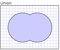
En el ejemplo siguiente, se define un CombinedGeometry con un modo de combinación de Union. Tanto Geometry1 como Geometry2 se definen como círculos del mismo radio, pero cuyos centros se desplazan por 50.
<Path Stroke="Black" StrokeThickness="1" Fill="#CCCCFF">
  <Path.Data>

    <!-- Combines two geometries using the union combine mode. -->
    <CombinedGeometry GeometryCombineMode="Union">
      <CombinedGeometry.Geometry1>
        <EllipseGeometry RadiusX="50" RadiusY="50" Center="75,75" />
      </CombinedGeometry.Geometry1>
      <CombinedGeometry.Geometry2>
        <EllipseGeometry RadiusX="50" RadiusY="50" Center="125,75" />
      </CombinedGeometry.Geometry2>
    </CombinedGeometry>
  </Path.Data>
</Path>
 Resultados del modo de combinación Uniónmil_task_combined_geometry_union
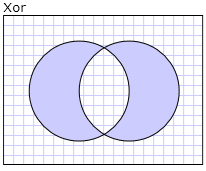
En el ejemplo siguiente, se define un CombinedGeometry con un modo de combinación de Xor. Tanto Geometry1 como Geometry2 se definen como círculos del mismo radio, pero cuyos centros se desplazan por 50.
<Path Stroke="Black" StrokeThickness="1" Fill="#CCCCFF">
  <Path.Data>

    <!-- Combines two geometries using the XOR combine mode. -->
    <CombinedGeometry GeometryCombineMode="Xor">
      <CombinedGeometry.Geometry1>
        <EllipseGeometry RadiusX="50" RadiusY="50" Center="75,75" />
      </CombinedGeometry.Geometry1>
      <CombinedGeometry.Geometry2>
        <EllipseGeometry RadiusX="50" RadiusY="50" Center="125,75" />
      </CombinedGeometry.Geometry2>
    </CombinedGeometry>
  </Path.Data>
</Path>
 Resultados del modo de combinación Xormil_task_combined_geometry_xor
Para obtener otros ejemplos, vea Create a Composite Shape (Cómo: Crear una forma compuesta) y Create a Combined Geometry (Cómo: Crear una geometría combinada).
Características de objeto Freezable
Como hereda de la clase Freezable, la clase Geometry presenta varias características especiales: los objetos Geometry se pueden declarar como recursos de XAML, compartirse entre varios objetos, convertirse en objetos de solo lectura para mejorar el rendimiento, clonarse y hacerse seguros para subprocesos. Para obtener más información sobre las diferentes características que ofrecen los objetos Freezable, consulte Información general sobre objetos Freezable.
Otras características de objeto Geometry
La clase Geometry ofrece también prácticos métodos de utilidad tales como los siguientes:
FillContains: determina si la geometría contiene otro Geometry.
StrokeContains: determina si el trazo de Geometry contiene un punto especificado.
Consulte la clase Geometry para ver una lista completa de sus métodos.
Consulte también
.NET Desktop feedback
