The IoT Journey: Working With Specialized Sensors
In previous posts in this series (see posts one, two, three and four) we’ve discussed the Raspberry Pi and it’s Linux-based operating system, along with the GPIO interface and using Visual Studio to develop applications in C# that execute on Linux using the Mono framework. Generally-speaking, this works well when the sensors you’re working with do not require critical timing or other “close to the hardware” code. Some sensors, however, have very time-critical components that require critical timing that just isn’t available in the Mono framework on Linux. An example is the DHT-11 Temperature and Humidity Sensor. This sensor is extremely popular because it’s very lightweight and simple from the hardware perspective, and requires only one channel to deliver both temperature and humidity readings. The DHT-11 can also be daisy-chained to provide a relatively wide-range of coverage.
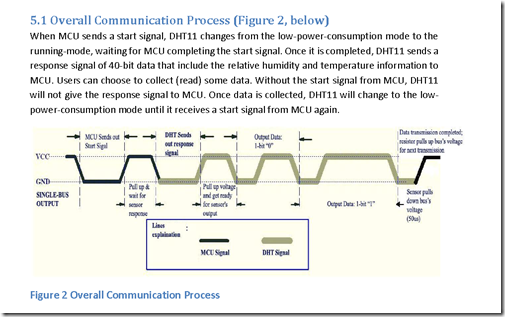
Unfortunately this simplicity from a hardware perspective comes at an expense: In order to interact with the DHT-11 and read the data that it provides, your code is extremely time-sensitive and must be able to precisely measure the digital signal state within just a few microseconds. If you look at the DHT-11 datasheet, you’ll find the following diagram:
This diagram explains how to read the DHT-11. Basically the process is:
- Send a “Start” Signal to the DHT-11 (Set the pin to LOW for 18 microseconds and then set it high for at least 20 microseconds)
- Wait for the DHT-11 to respond with a LOW signal for 80 microseconds followed by a HIGH signal for 80 microseconds
- Wait for the DHT-11 to send a “Start to transmit” signal (LOW for 50 microseconds)
- Time the HIGH pulse from the DHT-11
- If the signal width is between 26 and 28 microseconds, record a 0 for that bit
- If the signal width is 70 microseconds, record a 1 for that bit
- Repeat steps 3 and 4 until 40 bits of data have been transmitted (2 bytes for Temperature, 2 bytes for Humidity and 1 byte for the Checksum)
(I did warn in earlier posts that this series was going to get extremely geeky, but don’t worry, this is about as deep as it gets!)
Unfortunately my coding skills with C# and the Mono framework could not coax the DHT-11 into sending me any useful data. I believe that the timing is so critical that I could not get the managed code to respond with enough resolution to properly detect and read the signal transitions. (This is a major challenge when using PWM on a single signal without a buffer to communicate)
Fortunately though, we have access to C and C++ on the Raspberry Pi which will allow us to write code that will respond quickly enough to detect the transitions, and we can wrap that code in a library so that the majority of our code can still be written in C#. Before we get to that though, we will need to connect the DHT-11 to the Raspberry Pi.
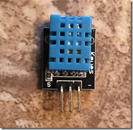
If you are using the Sensor Kit from Sunfounder as discussed in the second post in this series, you will have an already-mounted DHT-11 sensor with 3 pins. If not, there are several places where you can buy one, however if you’re going to play with IoT technologies and sensors, the best deal is the Sunfounder kit.
Step One – Wire the Circuit
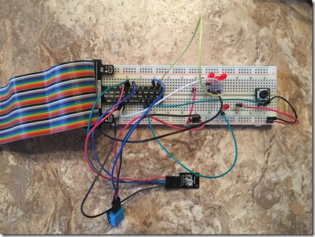
For this exercise, we will use the pushbutton circuit that we created in the last exercise with the RGB LED, as we will use the LED to report temperature and humidity status. On the DHT-11, the signal pin is the one closest to the S (far-left on the picture above). Connect this pin to GPIO 16 (physical pin 36) on the Pi, and then connect the middle pin (Vcc) to 3.3v on the breadboard, and then connect the last pin to ground on the breadboard. If you’re as messy with breadboard wiring as I am, your result will look like this:
We won’t use the pushbutton for this experiment, but no need to remove it from the breadboard. Now that the circuit is wired, we will need to code the solution.
Step Two – Prepare the Raspberry Pi
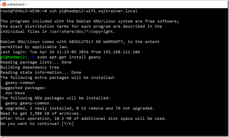
In order for this solution to work properly, we will need to develop some code in C++ that will interact directly with the DHT-11 sensor. You can do this in Visual Studio on Windows, however you will not be able to compile or debug the code there. In my experience, when developing new low-level code, it’s best to do it on the platform where the code will be executed. For this reason, we will want to use an IDE on the Pi directly. There are many developer GUIs available on the Pi, but the one that I’ve found easiest to use and does what I need is called Geany. In order to install and configure Geany, open an SSH session to your Pi and use apt-get install to install Geany. (Don’t forget to use sudo):
Answer Yes at the prompt. This will take several minutes to complete. Once Geany is installed, you will want to use VNC to connect to the Pi’s GUI environment. (See post one in this series for instructions on how to setup the VNC server – or you can follow the instructions here: https://www.howtogeek.com/141157/how-to-configure-your-raspberry-pi-for-remote-shell-desktop-and-file-transfer/all/)
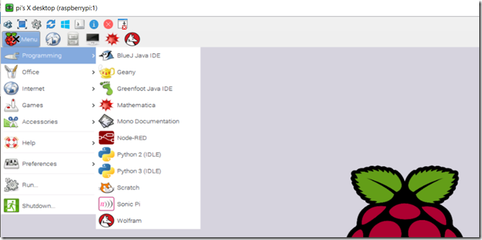
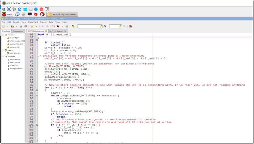
Once you are connected to the remote desktop session, you can start Geany (it will be available in the Programming menu) you are ready to begin coding the library necessary to communicate with the DHT-11 sensor.
Step Three – Develop the Sensor Library
The process outlined here will be the same for any time-sensitive code that you develop to interact with a sensor or peripheral device on the Pi. As it turns out the DHT-11, while seemingly complicated, is relatively straightforward once you understand the timing of the pulse and how to deal with it in code. If we were going to simply develop the entire program in C or C++, we wouldn’t need to create a library but would just write the code directly. Since we’re going to be wrapping this code with C#, we’ll create a shared library in C++ that will then be used by our main program.
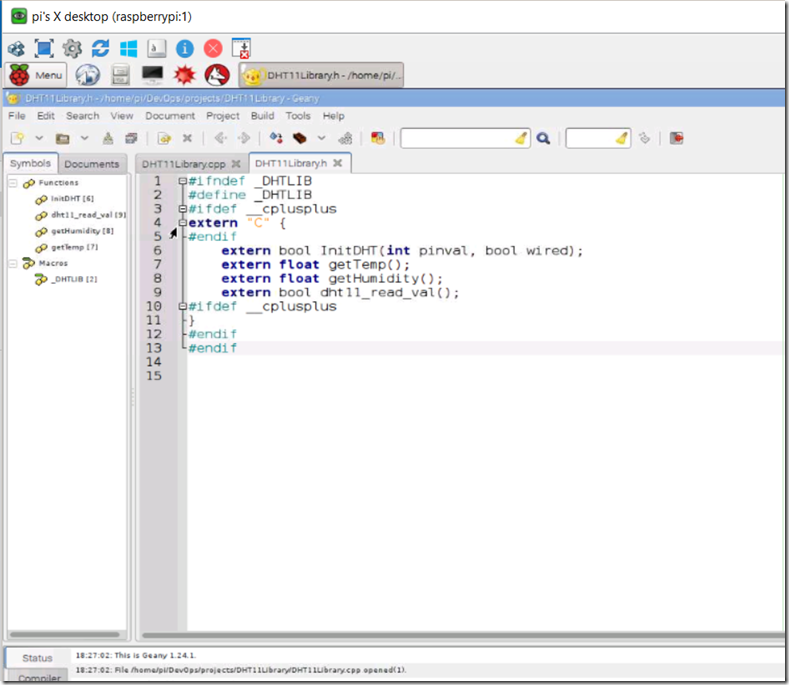
Since we are creating a library, we will need to define an interface that the code will use to interact with the library. We will do this by creating a header file. In my case I will be calling my library DHT11Library, so the header file will be called DHT11Library.h. In Geany, create a new c source file by selecting New with Template from the file menu and then select main.c as the template. Save the new file as DHT11Library.h and then add the following interface definition (I will add the full code to both files at the end of the article):
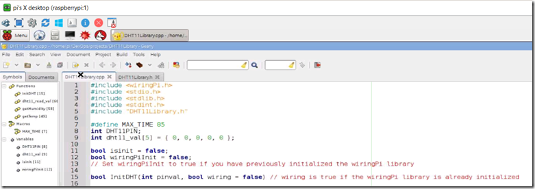
Once the interface is defined, create a new file using the main.c template and name it DHT11Library.cpp. In this file we will add the includes that we will need (don’t forget to include the DHT11Library.h file that we created previously, as well as setting up some global variables that we will need. Because we eventually want to use the DHT11 library with other sensors that have their own libraries, we will need a way to tell the wiringPi library that it has already been initialized. We will do that by calling the InitDHT method with a boolean that determines if you have already initialized the library. Because the WiringPi library is mostly static, we can only initialize WiringPi once. The DHT11Library that we will create here will allow for multiple instances to be instantiated, so we will track the status of the library by using a global variable called isinit. This looks like:
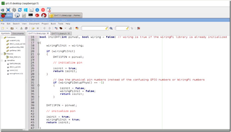
Next you will create the InitDHT method, where you will either initialize the WiringPi library as well as set the GPIO pin that the DHT11 is connected to. You will also test to see if the WiringPi library is already initialized:
Next we will create methods to retrieve the temperature and humidity from the DHT11 registers. The DHT11 was designed with 4 byte registers that hold the values. For temperature the first byte contains the integer portion and the second byte contains the decimal portion. However, as it turns out, while the DHT11 was designed this way, it actually doesn’t represent decimal numbers (the registers are always zero). I decided to treat the code as if the registers would be populated.. These methods look like:
Next we will create the method that actually reads data from the DHT11 registers. As discussed above, the DHT11 relies entirely on timing of the pulse-width in order to communicate data over the output back to the GPIO interface. For this method, we will need to setup a series of variables to use temporarily while everything is pulled together, and then send the start signal and wait for the sensor to respond:
Then, we verify that the checksum byte matches the result we expect and if so, return a valid read.
Once the values have been read and populated into the global variables that represent the byte registers, the code execution is complete.
Now that the code is complete, we will need to compile this into a shared library. The easiest way to do this is via the command line. Use the gcc command (and since you’re going to be creating a shared library, don’t forget sudo) as follows:
This will create the shared library on the Pi that will be available to the C# wrapper that we’ll create next.
Step Four – Develop the C# Wrapper Class
Now we will use Visual Studio on Windows in order to develop a wrapper class for the DHT-11 that will be used in our main program. Basically this class will follow the design principles that were laid out in post two in this series where we discussed the WiringPi wrapper class. The difference in this case is that we’ll develop this class on our own as opposed to using someone else’s work. Essentially what we will do is create a stand-alone class that will act as an entry point to the shared libDHT11.so that we just created. This class will simply mirror the interface that we specified, and will then implement the methods to read the temperature and humidity. We will also create a timer that will read the sensor on a regular basis.
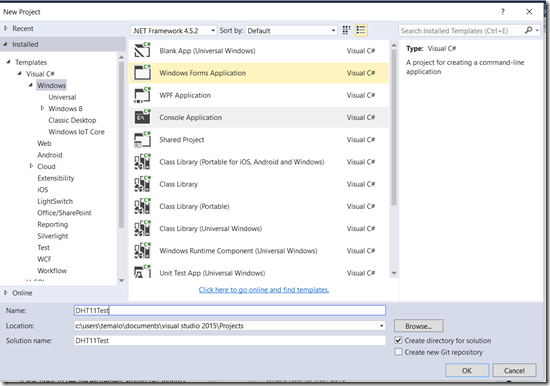
Open Visual Studio and create a new Windows C# Console application (Since we will be implementing the new class, we will just do it all in a single solution – for production purposes, you’ll likely want to create this class standalone to keep the namespace separate). Name the application DHT11Test.
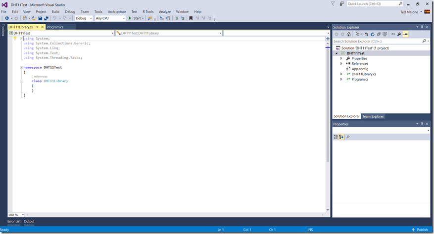
Once the solution has been created, add a new class named DHT11Library.
Once the new class has been added to the solution, we will want to add the environment information necessary to instantiate the DHT11Library. At a high level, the new class will consist of the following:
- An embedded class to hold the temperature and humidity values. We will use this as the basis for an event that will let us know when the DHT11 has reported new data. Since the actual reading of data from the sensor is a time-sensitive process, we will need a place to store the data when it arrives, even if we’re not quite ready to use it.
- A wrapper for the C++ library that we created (effectively the interface)
- Global variables that represent the pin that the sensor is connected to, the desired delay between reads, data from the sensor and whether the GPIO interface is already initialized
- A timer that will initiate the read process from the sensor
- A delegate that will allow us to asynchronously read the sensor
- A constructor for the class
- Start and Stop methods for the timer
- A method to return the sensor data
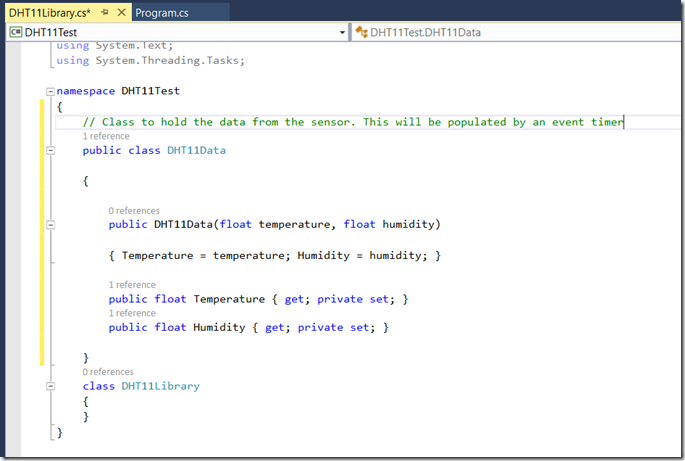
In the namespace declaration of the new class you added, create the class that will hold the temperature and humidity values. These values will be float types (although we could get away with integer values due to the resolution of the sensor). They will need constructors as well. You also need to add using statements for System.Timers and System.Runtime.InteropServices
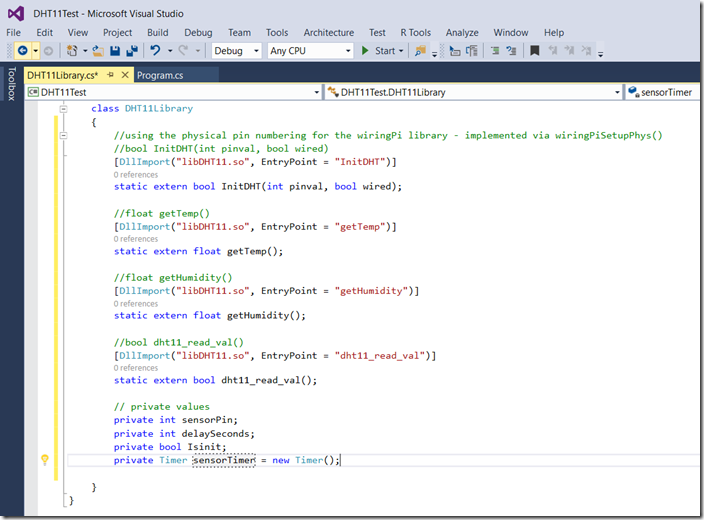
Then you will need to add the wrapper as well as the private variables for the class:
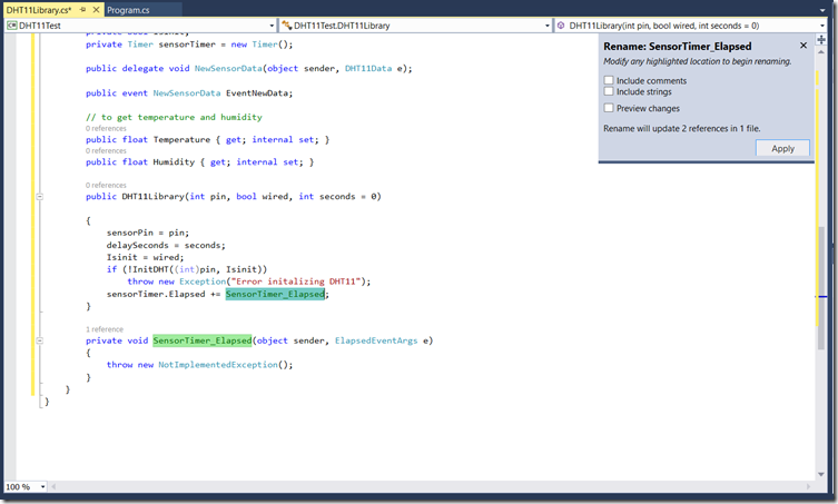
Once this is complete you will need to create the delegate for the async call as well as the event to read data. You also need to create the constructor for the class along with the stub for the elapsed timer:
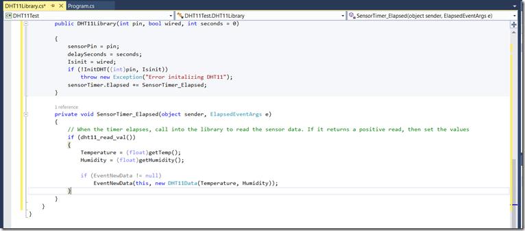
Next, you will need to implement the elapsed handler for the timer:
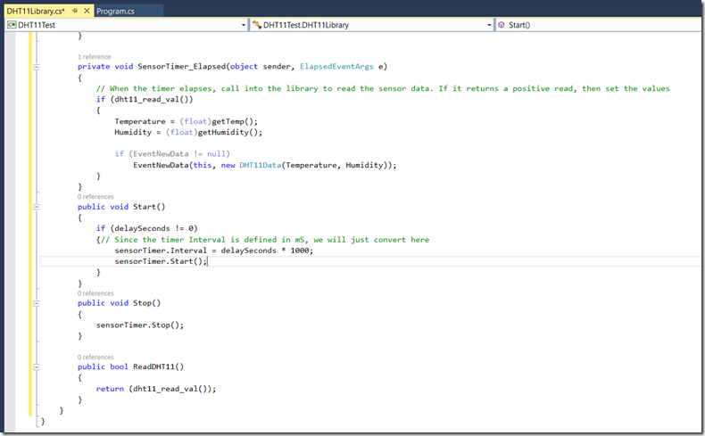
Then we need to create the start and stop methods for the timer, along with the method to read from the sensor.
Once this is complete, we can save the class file and move to the program that we will use to instantiate the class.
Step Five – Develop the Application to Read from the Sensor
Finally, we can get to the actual implementation of all the code. As mentioned above, we will use the RGB Led that we worked with in the last post in this series along with the sensor to provide a visual status of the operation. The flow of the program will be:
- Initialize the GPIO Ports on the Raspberry Pi and setup Pulse Width Modulation for the RGB LED
- Turn the RGB LED Red
- Instantiate the DHT11 Class
- Turn the RGB LED Green
- Setup the event handler for new data
- Start the timer
- Read the Sensor and convert temperature to Fahrenheit
- Turn the RGB LED to Blue during the read operation (and delay for 1/2 second so you can witness the change)
- Turn the RGB LED Green on successful read, or Red if there is a problem
- Write the temp and humidity to the console
- Check for a keypress, and if detected, close down the sensor and exit
The code for the above flow looks like this:
using System;
using WiringPi;
namespace DHT11Test
{
class Program
{
const int DHTPin = 36; //DHT Signal on GPIO 16 (Physical pin 36)
const int Delay = 3; // 3 second delay between readings
const int LedPinRed = 16; // Red Pin of RGB LED
const int LedPinGreen = 18; // Green Pin of RGB LED
const int LedPinBlue = 22; // Blue Pin of RGB LED
static void Main(string[] args)
{
if (Init.WiringPiSetupPhys() != -1) // Call the physical pin numbering instead of the confusing WiringPi numbering
{
GPIO.SoftPwm.Create(LedPinRed, 0, 100); // Setup the Pulse-Width-Modulation libary and initialize the RGB LEDs
GPIO.SoftPwm.Create(LedPinGreen, 0, 100);
GPIO.SoftPwm.Create(LedPinBlue, 0, 100);
SetLedColor(255, 0, 0); // Set the RGB to Red and turn it on
Console.WriteLine("GPIO Initialized");
Console.WriteLine("Initializing DHT11 Sensor!");
DHT11Library DHT = new DHT11Library(DHTPin, true, Delay); // Instantiate the DHT11 Class and tell it that the WiringPi library is already initialized
Console.WriteLine("Sensor Initialized on Pin: " + DHTPin.ToString());
Console.WriteLine("By default, readings occur every 3 seconds");
DHT.EventNewData += DHT_EventNewData;
DHT.Start();
SetLedColor(0, 255, 0); // Set the RGB to Green
Console.WriteLine("Press any key to exit");
Console.ReadKey();
DHT.Stop(); // Stop the sensor readings
GPIO.SoftPwm.Stop(LedPinRed); // Shut down the PWM
GPIO.SoftPwm.Stop(LedPinGreen);
GPIO.SoftPwm.Stop(LedPinBlue);
}
}
private static void DHT_EventNewData(object sender, DHT11Data e)
{
SetLedColor(0, 0, 255); // Turn the RGB LED to Blue
double TempF = e.Temperature * 1.8 + 32;
Console.WriteLine("Temperature: " + e.Temperature + " Degrees (C), " + TempF + " Degrees (F), Humidity: " + e.Humidity + "%");
System.Threading.Thread.Sleep(500); // Delay for 1/2 second so you can see the LED change color
SetLedColor(0, 255, 0); // Turn the RGB LED to Green
}
private static void SetLedColor(int r, int g, int b)
{
GPIO.SoftPwm.Write(LedPinRed, r);
GPIO.SoftPwm.Write(LedPinGreen, g);
GPIO.SoftPwm.Write(LedPinBlue, b);
}
}
}
Once this is complete, build the solution and prepare to copy it to the Pi
Step Six – Deploying and Testing the Application
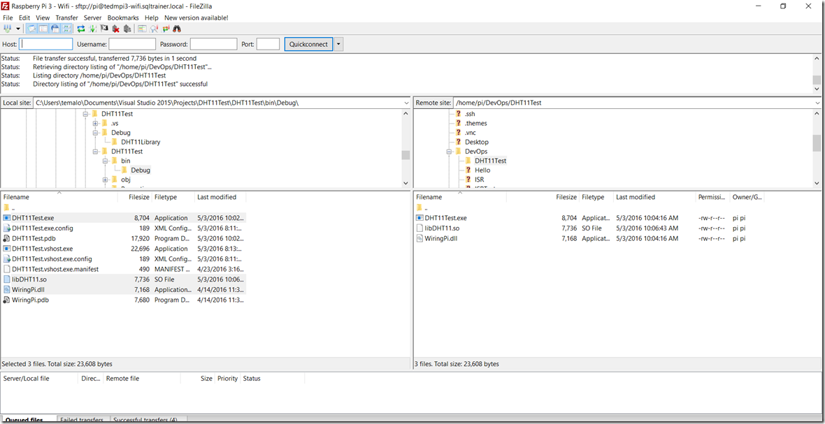
As we have done in previous posts, you will want to create a deployment folder on your Pi and copy the executable and DLL to the Pi. I use FileZilla for the copy operation. You will need to copy the libDHT11.so file that you created on the Pi into the destination folder as well. For simplicities sake, I use FileZilla to copy the file from the Pi into the project folder on my development machine so that I always have it available when I deploy, but you can also simply copy the file on the Pi as well. You need a total of 3 files on the Pi in order to execute this application.
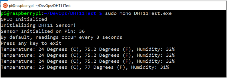
Once the code is deployed, execute using the sudo command:
You should see the following. Note that the temperature readings do not always appear at 3 second intervals. Sometimes the timing call to the DHT does not properly retrieve the temperature, so you wait a cycle or two for it to write data. This is just the nature of the 3 second delay. In a true production application, we likely would not be reading the temperature every 3 seconds.
Congrats! You have just developed and deployed an application that uses PWM to communicate with a sensor to retrieve data.
In the next post in this series, we will begin the process of communicating the results of this data to the Azure IoT Suite so that we can use it.
