Compiling C# Programs to FPGA Circuits: An Ethernet Packet Processing Example
In a previous blog article I showed how to get the default Ethernet address swap circuit working on the ML605 board. The address swap module (which can be generated in VHDL or Verilog) is tedious to write yourself because you have to explicitly write it as a state machine. In typical hardware description languages you have "lost the semicolon" and the program you write very much resembles coding with call-backs in GUIs or REST-style programming or writing directly in continuation passing style. With David Greaves at the University of Cambridge I've been working on a system called Kiwi which tries to civilize hardware design by allowing us to model circuit behaviour with multi-threaded C# programs (or any other .NET language) and then have these programs automatically converted into Verilog hardware descriptions ready for implementation on FPGAs.
The code below describes a circuit which processes raw Ethernet packets and is designed to mimic the hand written VHDL or Verilog that comes with the Ethernet wrapper provided by Xilinx. It's job is to read a packet into memory, swap the source and destination MAC addresses and send the packet back out. Unlike the VHDL or Verilog versions this circuit stores the whole packet in memory and can crawl over it at line speed to perform various kinds of inspections (e.g. for a virus) or processing operations (e.g. for manipulating Ethernet packets as they flow through the network).
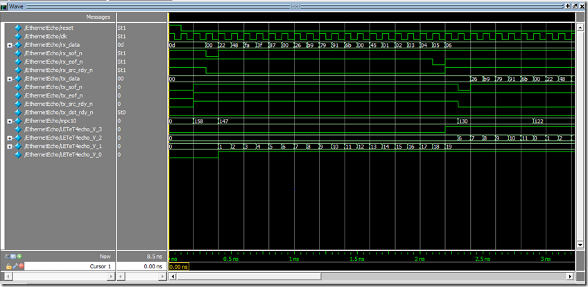
The circuit works at the level of the LocalLink protocol which is used to wrap the raw Ethernet level signals to make it easier to send and receive frames and to do flow control. Our objective is to generate a behaviour like this (simulator output):
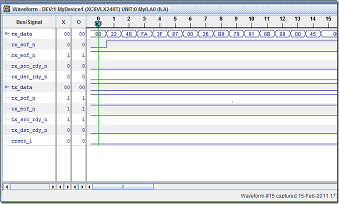
or this (output from live running circuit running on the ML605 board using a logic analyser):
until the end of this incoming frame and then generate the outgoing frame with the MAC address swapped i.e. 00:22:48:FA:3F:87swapped with 00:26:B9:79:91:6B
Here's the C'# source to perform the Ethernet echo with the MAC address swap:
 using KiwiSystem;

class LocalLinkLoopBackTest
{
    static byte[] buffer = new byte[1024];

    class EthernetEcho
    {
        [Kiwi.Hardware()] // This class should be implemented in hardware

        // This class describes a circuit which echos a raw Ethernet frame
        // and is designed to mimic the functionality of the address swap
        // module provided by the Xilinx Core Generator Tri-Mode Ethernet MAX wrapper.

        // DST is this hardware module
        // SRC is the other end (e.g. test bench or the Ethernet MAC interface)
        // RX is the incoming data
        // TX is the outgoing data


        // These are the ports of the circuit (and will appear as ports in the generated Verilog)
        [Kiwi.InputWordPort("rx_data")]
        static byte rx_data;        // Write data to be sent to device
        [Kiwi.InputBitPort("rx_sof_n")]
        static bool rx_sof_n;       // Start of frame indicator
        [Kiwi.InputBitPort("rx_eof_n")]
        static bool rx_eof_n;       // End of frame indicator
        [Kiwi.InputBitPort("rx_src_rdy_n")]
        static bool rx_src_rdy_n;   // Source ready indicator
        //[Kiwi.OutputBitPort("rx_dst_rdy_n")]
        //static bool rx_dst_rdy_n;   // Destination ready indicator

        [Kiwi.OutputWordPort("tx_data")]
        static byte tx_data;        // Write data to be sent to device
        [Kiwi.OutputBitPort("tx_sof_n")]
        static bool tx_sof_n;       // Start of frame indicator
        [Kiwi.OutputBitPort("tx_eof_n")]
        static bool tx_eof_n;       // End of frame indicator
        [Kiwi.OutputBitPort("tx_src_rdy_n")]
        static bool tx_src_rdy_n;   // Source ready indicator
        [Kiwi.InputBitPort("tx_dst_rdy_n")]
        static bool tx_dst_rdy_n;    // Destination ready indicator

        // Thus buffer stores an incoming Ethernet frame
        static byte[] buffer = new byte[1024];

        // This method describes the operations required to echo the Ethernet frame
        static public void echo()
        {

            tx_sof_n = !false; // We are not at the start of a frame
            tx_src_rdy_n = !false;
            tx_eof_n = !false; // We are not at the end of a frame
            bool start = !rx_sof_n && !rx_src_rdy_n; // The start condition
            int i, j;
            bool doneReading;

            while (true) // Process packets indefinately
            {
                // Wait for SOF and SRC_RDY
                while (!start)
                {
                    Kiwi.Pause(); // Wait for a clock tick
                    start = !rx_sof_n && !rx_src_rdy_n; // Check for start of frame
                }

                // Read in the entire frame
                i = 0;
                doneReading = false;

                // Read the remaining bytes
                while (!doneReading)
                {
                    if (!rx_src_rdy_n)
                    {
                        buffer[i] = rx_data;
                        i++;
                    }
                    doneReading = !rx_eof_n;
                    Kiwi.Pause();
                }

                tx_src_rdy_n = !true; // We are not at the start of a frame

                // Now send an Ethernet packet back to where it came from

                // Swap source and destination MAC addresses
                j = 0;
                tx_sof_n = !false;
                for (j = 6; j < 12; j++) // Process a 6 byte MAC address
                {

                    tx_data = buffer[j];
                    tx_sof_n = j != 6;
                    Kiwi.Pause();
                }
                for (j = 0; j < 6; j++) // Process a 6 byte MAC address
                {
                    tx_data = buffer[j];
                    Kiwi.Pause();
                }

                // Transmit the remaining bytes
                j = 12;
                while (j < i)
                {
                    tx_data = buffer[j];
                    if (j == i - 1)
                        tx_eof_n = !true;

                    j++;
                    Kiwi.Pause();
                }
                tx_src_rdy_n = !false;
                tx_eof_n = !false;
                start = false; // No longer at start of frame
                Kiwi.Pause();
                // End of frame, ready for next frame
            }
        }
    }
Compared to VHDL or Verilog it is very convenient to be able to use normal programming language control flow constructs. This makes Kiwi convenient for writing sophisticated network processing algorithms in a "direct" style rather than explicitly coding finite state machines. Furthermore, the circuit can be tested in Visual Studio using regular debugging and code analysis tools.
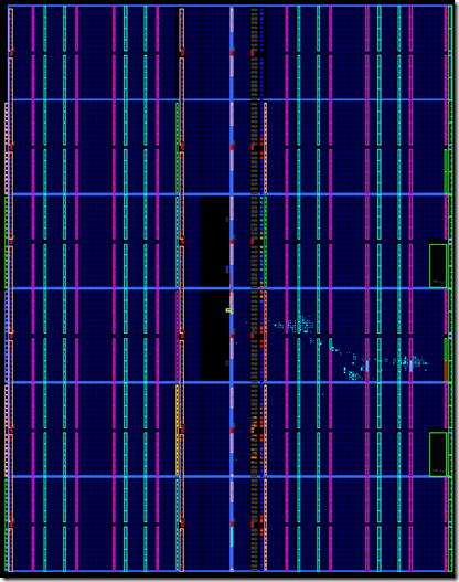
The generated Verilog can be simulated or turned into an FPGA circuit using the Xilinx design tools e.g. on this XC6VLX240T chip (it's the light blue dots on the right hand side):
We chose a 125MHz clock to drive our packet processing circuit although the circuit is capable of running much faster. You can find out more about Kiwi by looking at the papers on my Microsoft website.
A small part of the code above (a simpler shift register variant rather than storing the whole packet) in VHDL would look like this (yuk!):
 control_fsm_sync_p : process(rx_ll_clock)
   begin
      if rising_edge(rx_ll_clock) then
         if rx_ll_reset = '1' then
            control_fsm_state <= wait_sf;
         else
           if rx_enable = '1' then
             case control_fsm_state is
                when wait_sf =>
                   if sof_sr_content(4) = '1' then
                      control_fsm_state <= bypass_sa1;
                   else
                      control_fsm_state <= wait_sf;
                   end if;

                when bypass_sa1 =>
                   if not(sof_sr_content(4) = '0' and eof_sr_content(4) = '1') then
                      control_fsm_state <= bypass_sa2;
                   else
                      control_fsm_state <= wait_sf;
                   end if;

                when bypass_sa2 =>
                   if not(sof_sr_content(4) = '0' and eof_sr_content(4) = '1') then
                      control_fsm_state <= bypass_sa3;
                   else
                      control_fsm_state <= wait_sf;
                   end if;

                when bypass_sa3 =>
                   if not(sof_sr_content(4) = '0' and eof_sr_content(4) = '1') then
                      control_fsm_state <= bypass_sa4;
                   else
                      control_fsm_state <= wait_sf;
                   end if;

                when bypass_sa4 =>
                   if not(sof_sr_content(4) = '0' and eof_sr_content(4) = '1') then
                      control_fsm_state <= bypass_sa5;
                   else
                      control_fsm_state <= wait_sf;
                   end if;

                when bypass_sa5 =>
                   if not(sof_sr_content(4) = '0' and eof_sr_content(4) = '1') then
                      control_fsm_state <= bypass_sa6;
                   else
                      control_fsm_state <= wait_sf;
                   end if;

                when bypass_sa6 =>
                   if not(sof_sr_content(4) = '0' and eof_sr_content(4) = '1') then
                      control_fsm_state <= pass_rof;
                   else
                      control_fsm_state <= wait_sf;
                   end if;

                when pass_rof =>
                   if not(sof_sr_content(4) = '0' and eof_sr_content(4) = '1') then
                      control_fsm_state <= pass_rof;
                   else
                      control_fsm_state <= wait_sf;
                   end if;

                when others =>
                   control_fsm_state <= wait_sf;

                end case;
             end if;
           end if;
      end if;
   end process;  -- control_fsm_sync_p

   ----------------------------------------------------------------------------
   --Process control_fsm_comb_p
   --Determines control signals from control_fsm state
   ----------------------------------------------------------------------------
   control_fsm_comb_p : process(control_fsm_state)
   begin
      case control_fsm_state is
         when wait_sf    =>
            sel_delay_path <= '0';  -- output data from data shift register
            enable_data_sr <= '1';  -- enable data to be loaded into shift register

         when bypass_sa1 =>
            sel_delay_path <= '1';  -- output data directly from input
            enable_data_sr <= '0';  -- hold current data in shift register

         when bypass_sa2 =>
            sel_delay_path <= '1';  -- output data directly from input
            enable_data_sr <= '0';  -- hold current data in shift register

         when bypass_sa3 =>
            sel_delay_path <= '1';  -- output data directly from input
            enable_data_sr <= '0';  -- hold current data in shift register

         when bypass_sa4 =>
            sel_delay_path <= '1';  -- output data directly from input
            enable_data_sr <= '0';  -- hold current data in shift register

         when bypass_sa5 =>
            sel_delay_path <= '1';  -- output data directly from input
            enable_data_sr <= '0';  -- hold current data in shift register

         when bypass_sa6 =>
            sel_delay_path <= '1';  -- output data directly from input
            enable_data_sr <= '0';  -- hold current data in shift register

         when pass_rof   =>
            sel_delay_path <= '0';  -- output data from data shift register
            enable_data_sr <= '1';  -- enable data to be loaded into shift register

         when others     =>
            sel_delay_path <= '0';
            enable_data_sr <= '1';

      end case;
   end process;  -- control_fsm_comb_p
Comments
- Anonymous
March 21, 2011
The comment has been removed


