VSTS 2010 Architecture: [Part One] Model Project
In my last post, I began talking about the logical structure of the VSTS 2010 Architecture product. I now want to start drilling into the various areas I outlined in that post. In this post, I want to start going deeper in the "Team Collaboration" area, specifically talking about some details around the new project type we've created, currently called ( amazingly enough ), the "Modeling Project".
This new modeling project will be container for modeling data, diagram files, and any other artifacts that you'd like to store ( such as Word docs for instance ). The new project can be inserted into any existing or new solution you would like to create, and can sit happily along with your other projects ( C# / VB / Web, etc. ), and can be version controlled just like any other project.
Let me give you taste of some of the details.
Modeling Project
In the 2010 CTP, you will see a new project template when you go to create a new project in Visual Studio, as seen in the figure below.
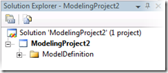
Clicking on the OK button results in a new modeling project inside the Visual Studio Solution Explorer:
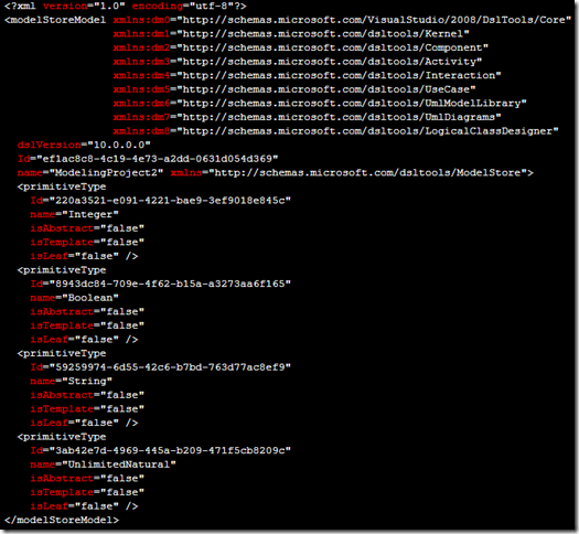
Inside the "ModelDefinition" folder is a file called "ModelDefinition.uml". In the 2010 CTP, this file holds all the data that will represent the various UML models you will be creating later on. Let's take a look at the file right after project creation:
Obviously, an XML file whose root element is the "modelStoreModel". I'll come back to this in a moment. I want to first start to point out the changes to the file after adding one Logical Class diagram and dropping one class element on that diagram. Let's do that now.
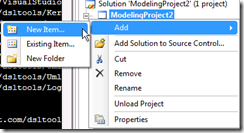
Right click on the root of the ModelingProject2 project node, like so:
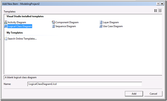
You'll be presented with the following dialog:
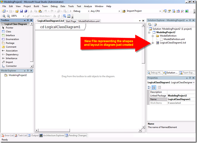
Let's just take the defaults, hit the "Add" button. Now our modeling project looks like this:
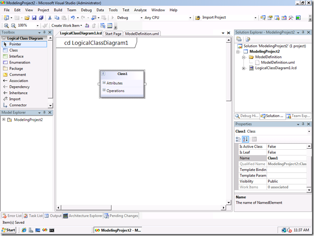
Now let's add one class element to the new diagram, by clicking on the "Class" tool in the Toolbox, and then dropping onto the active diagram we just created. ( See this post for other tips on how to "lock" the tool box items in order to drop many items at once ).
So now the diagram looks like this, after saving all:
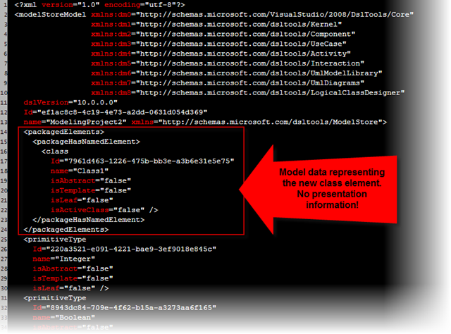
Now let's look at the changes in the ModelDefinition.uml file:
You'll notice that the only thing that has changed is the addition of the class information, plus some encapsulating xml elements that I'll discuss in a later post. The bit that I want to emphasize right now is that the data found in the ModelDefinition.uml file is *only* data about the model elements themselves, and not about how those elements are presented on a diagram. You will see no positional information, no information about color, or even information that this particular element is present on the LogicalClassdiagram1 diagram. Complete separation of model data and presentation data is maintained at all times.
In the CTP bits, no matter how many model elements you create in the various UML diagrams we have in the product, you will only see this one file getting bigger and bigger in size on disk. This is *not* how we will ship. For every package element, a new file will be created and stored on disk in the ModelDefinition folder. The idea here is that this will help mitigate the likelihood of merge conflicts that can occur, once the modeling project has been version controlled. It will certainly mitigate that problem much better than everything going into one file!
So where is the presentation information housed? The diagram files themselves.
Team Collaboration
So why do I lump this new Modeling Project into the "Team Collaboration" area in my first post in this series? Because this new project will be one of the primary ways of sharing the data associated with your new models with the rest of your development organization via the version control system currently deployed.
You will of course be able to share your models with others via printing, emailing of copied diagram elements, etc., but being able to check those models into source control right along and next to the rest of the source that make up your system will be a significant productivity aid.
But what will happen if one of your developers does not have the 2010 Architecture box installed on their box? Will the solution that contains one of these modeling projects load? Will that developer be able to view the diagrams? The answer to all those questions is *yes* . The only thing the developer without the Architecture box will not be able to do is change the data behind the models they are viewing. The will be able to load the modeling project, double click and view the diagrams, select elements, look at their properties, zoom in and out on the diagram, etc. They just can't change or add model data.
Summary
The new modeling project in 2010 Architecture will house all the relevant artifacts associated with your models. It will hold the data for the models themselves, the diagrams that visualize that data, as well as other artifacts you find important enough to house inside the same project, such as word documents, power point slides, etc. That modeling project can then be version controlled and shared with the rest of your team.
Comments
- Anonymous
November 16, 2008
PingBack from http://mstechnews.info/2008/11/vsts-2010-architecture-part-one-model-project/ - Anonymous
November 18, 2008
Patrice Calve on Migrating VSS 2005 to TFS 2008 Ayman Badawi on TFS 2008 Web Services List Brian Harry... - Anonymous
November 19, 2008
How much traceability do these modelling projects provide? Are links established and maintained with other code-based projects inside your solution?It would be really useful for a developer to be able to drill-up and see for example the use case they are currently working on. - Anonymous
November 19, 2008
Hello Paul,Nothing about the project itself will actually create those types of links for you automatically. However, a feature that I have alluded to but have not shown yet is the ability to link model elements ( or whole diagrams ) with any type of Work Item you see Team Foundation Server. So if you have your requirements in TFS ( think of a requirement in TFS as a special kind of Work Item ), you can link model elements to that. This is interesting in your scenario 'cause when a dev is going to check in a change set for example, they can associate that changeset ( changeset being a collection of artifacts being checked in ) to any work item as well.Depending on how you have linked these various work items, you can then run queries to see the trace relationships.This warrants a complete post in and of itself to drive the details home.I'll do that soon. ;)Thanks Paul!Cameron - Anonymous
November 23, 2008
In my last post , I introduced the Modeling project that will be introduced in the VSTS 2010 Architecture - Anonymous
February 01, 2009
The comment has been removed - Anonymous
June 08, 2009
Can it do reverse engineering and generate UML sequence/activity diagram out of project source code? - Anonymous
June 08, 2009
You can create a UML Sequence diagram by right clicking on a method in the Visual Studio Text Editor ( C# or VB supported ). We don't support creation of an activity graph directly from source however. - Anonymous
November 02, 2011
Ok, so lets get this right the diagrams defintion files (xml) are hard linked to the usecases.uml model defintion through guid connectors. That means the two files are tightly coupled. If any one of the files is corupt then your entire modeling project is probably bust. And because we are using xml files (that arent merged easily anyway) with guids this compounds the problem. Forget about two people working within the same modeling project at the same time. Just pray that one of your files never goes corrupt. Im not sure who at microsoft thinks that embedding guids into xml files is a good idea. It looks like whoever designed SSIS also designed this, but with SSIS at least all of your guids were within the same file.

