Coordinate Systems (Direct3D 10)
Coordinate systems for Direct3D 10 are defined for pixels and texels.
Differences between Direct3D 9 and Direct3D 10:
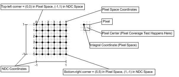
- Direct3D 10 defines the upper-left corner of the upper-left pixel as the origin of a render target.
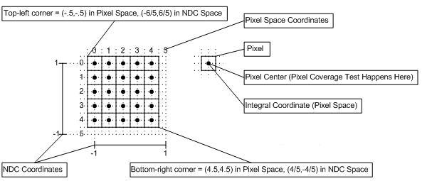
- Direct3D 9 defines the center of the upper-left pixel as the origin of a render target.
Pixel Coordinate System
The pixel coordinate system in Direct3D 10 defines the origin of a render target at the upper-left corner. as shown in the following diagram. Pixel centers are offset by (0.5f,0.5f) from integer locations.

Pixel Coordinate System for Direct3D 9
For reference, here is the pixel coordinate system for Direct3D 9, which defined the origin or a render target as the center of the upper-left pixel, (0.5,0.5) away from the upper left corner, as shown in the following diagram. In Direct3D 9, pixel centers are at integer locations.

Texel Coordinate System
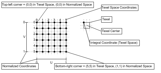
The texel coordinate system has its origin at the top-left corner of the texture, as shown in the following diagram. This makes rendering screen-aligned textures trivial (in Direct3D 10), as the pixel coordinate system is aligned with the texel coordinate system.

Texel Coordinate System
Texture coordinates are represented with either a normalized or a scaled number; each texture coordinate is mapped to a specific texel as follows:
For a normalized coordinate:
- Point sampling: Texel # = floor(U * Width)
- Linear sampling: Left Texel # = floor(U * Width), Right Texel # = Left Texel # + 1
For a scaled coordinate:
- Point sampling: Texel # = floor(U)
- Linear sampling: Left Texel # = floor(U - 0.5), Right Texel # = Left Texel # + 1
Where the width, is the width of the texture (in texels).
Texture address wrapping occurs after the texel location is computed.
Related topics