How to use the Precision Touch Testing Tool
The Precision Touch Testing Tool, or PT3, is a multi-function tool that tests high-performance touch digitizers against the Windows Hardware Lab Kit touch tests for Windows 8. It can operate at performance levels where human operator precision is not sufficient. It can tap precisely at a defined point, realign quickly, perfectly trace up to five straight lines simultaneously, draw fixed-radius curves, and support adjustable distances between adjacent contacts.
The PT3 does all of these tasks well, but its capable performance does not make these tasks trivial. You must practice and prepare to become comfortable using the PT3.
Terminology and Visual Orientation
The following images show the terminology and visual orientation of the PT3 that is referenced in this topic.
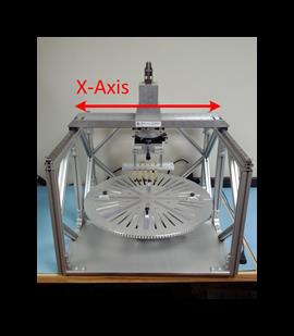
Figure 1: X-axis
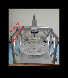
Figure 2: Y-axis
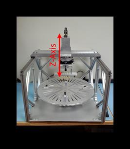
Figure 3: Z-axis
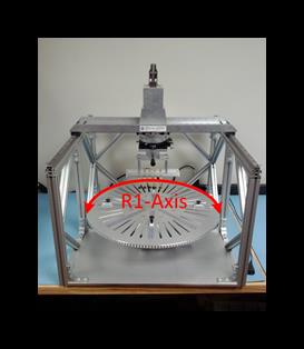
Figure 4: R1-axis
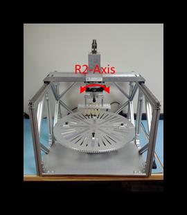
Figure 5: R2-axis
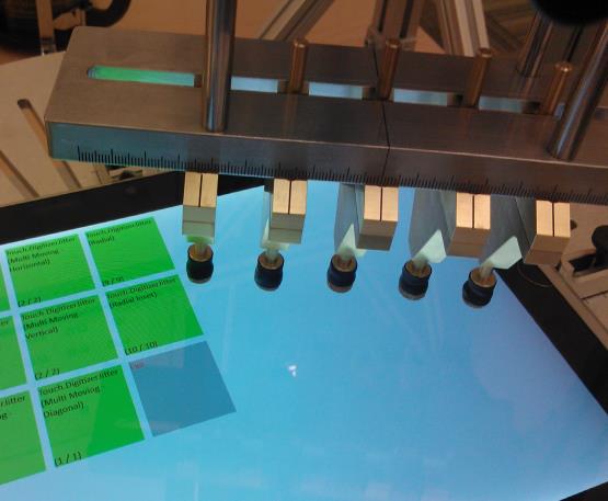
Figure 6: Actuators in the carriage
In addition:
The R2 Axis is also referred to as the base plate.
The R1 Axis is also referred to as the rotational stage.
DUT stands for Device Under Test.
An Actuator is a finger-like module used to deliver a touch to the screen. Five actuators are shown in Figure 6.
The Carriage is the metal piece that holds the actuators. Shown in Figure 6.
Basic Usage
Place the DUT into the housing
The PT3 has four locks to fix the DUT into the housing. We recommend that you position the device so that the center of its screen is concentric with the base plate; this will make alignment easier in many cases. A scale is drawn on the plate to facilitate this. The gap in the center of the base plate is 3 cm in diameter.
We recommend that you position the device so that the device faces the tester in the 0° position.
Position an actuator and make contact
The actuator housing moves freely along four axes: horizontally and vertically in the plane of the base plate, up and down perpendicular to the base plate (Z-axis), and rotationally in the plane of the base plate.
You can restrict motion along the X-axis and Y-axis by using the locks that are found on the rails, as shown in figures 1 and 2. You can restrict rotational motion by turning the knob that is located on the side of the actuator housing (shown in figure 5).
The actuator (or actuators) is brought into contact with the screen by using the red lever on top of the actuator housing, which moves the actuators along the Z-axis. When five actuators are placed in the carriage, the spring will balance the actuators so that they can remain floating in position.
The user interface (UI) of the Windows Hardware Lab Kit (Windows HLK) tests provides affordances for performing precise targeting. Each target is rendered as a set of crosshairs inside a pair of concentric circles. The inner circle, which is colored green or yellow, has a diameter of 9 mm, while the outer circle has a diameter of 10 mm. Position the actuator so that it is contained in the inner circle as best as you can. Use the crosshairs to better position the center of the actuator at the center of the target.
Trace a line
Linear motion is generally performed along the Y-axis, with the X-axis and rotational stage locked. This provides maximum ease of use. Alignment is generally done as follows:
Lock the rotational stage at 0°.
Move the actuator housing along the X-axis and position it over the starting target, which will be green.
Roughly align the on-screen line to the Y-axis by rotating the base plate.
Without bringing the actuator into contact with the screen, trace the on-screen line to its terminus at the yellow target. Use the fine-adjustment knob to correct the alignment.
Repeat steps 2 through 4 until a line can be traced from the center of the green target to the center of the yellow target.
Shortcuts
When the following conditions are met, you can save a significant amount of time in aligning the actuator(s):
The screen is rectangular.
Adjacent edges on the device are at 90° to each other.
In this case, you can use the R1 axis to perform all of the alignment in horizontal and vertical cases simply by locking the rotational (R2) stage at 0° and positioning the R1-axis at 0°, 90°, 180° or 270°, as the situation dictates.If the screen is centered on the device, and the device itself is centered in the PT3, you can use the 45° angles on the rotational stage to perform diagonal alignment.
Trace a curve
Curves are traced by using the motion of the R2-axis, or rotational stage. The center of the carriage is clearly marked, so that circles of varying radii can quickly be configured. The test uses three radii: 1.2 cm, 3 cm, and 3.2 cm.
To trace the curve, first align over the starting point, or points, of the motion. Then, lock the motion of the x and y axes by using the lock switches. Finally, use the handle that is attached to the actuator housing to rotate around the center of the carriage.
Adjust the Actuators
Actuators are affixed to the carriage by magnets. To add an actuator, simply place it into the concave underside of the carriage until it snaps into place. To remove an actuator, tilt it until it becomes free and pull it down and out of the carriage.
You can set the position of the actuator in one-millimeter increments by using the scale on the carriage. For example, this lets you set five contacts at mutual center-to-center distances of 13 mm to execute the horizontal and vertical Input Separation tests.
Running the Tests
Three test jobs require the use of precision tools to be successful (although it is not necessarily true that each case within a test job requires precision tools). This section describes how to use the PT3 to pass these test jobs.
Digitizer Jitter
Single Stationary
Configuration:
One actuator
Rotational stage locked
To execute these test cases, position the actuator over the green area and lock both the X and Y axes. Once this is done, pull the lever to make contact with the screen, and hold contact for at least one second. Repeat for each target until the test is complete.
Multi Stationary
Configuration:
Five actuators
At least 20 mm between adjacent actuators
Rotational stage locked
To execute this test, position all actuators over the green area and lock both the X and Y axes. Then, pull the lever to make contact with the screen, and hold contact for at least 15 seconds. Repeat for each target until the test is complete. Note that bringing the actuators into contact too quickly can cause them to bounce on the screen, resulting in a failure. We recommend that the actuators be brought down slowly and be allowed to remain in contact for more than 15 seconds.
Single Moving
Configuration:
One actuator
Rotational stage locked
There are four different cases: horizontal, vertical, diagonal (left to right) and diagonal (right to left). Each case is run the same way.
First, align the motion to the line rendered on the screen by following the instructions in the Basic Usage section of this topic. Position the actuator over the green target, so that the contact area of the actuator is inside the green area. Use the concentric circles and crosshairs as a guide. Bring the actuator into contact with the screen at the center of the green target and drag to the center of the yellow target. There is no minimum or maximum speed.
Multiple Moving
Configuration:
Five actuators
At least 20 mm between adjacent actuators
Rotational stage locked
There are four different cases: horizontal, vertical, diagonal (left to right) and diagonal (right to left). Each case is run the same way.
First, align the motion to the lines rendered on the screen by following the instructions in the Basic Usage section of this document. Position the actuators over the green targets, so that the contact area of each actuator is inside the green area of its corresponding target. Use the concentric circles and crosshairs as a guide. Bring the actuators into contact with the screen at the centers of the green targets and drag to the centers of the yellow targets. There is no minimum or maximum speed.
Note
It is important that the R2-axis be locked to the 0° position, or it will be more difficult to align the actuators to the targets.
Radial
Configuration:
Two actuators
Each actuator is placed 3 cm from the center of the carriage
Rotational stage unlocked
This test has been divided into two areas: one to cover the left side of the screen, and one to cover the right side of the screen.
First, fix two actuators to the carriage at a distance of 5 cm from the center. Position each actuator above a green target and make sure that it is centered. Then, rotate in the direction that is indicated by the lines that are rendered on the screen until the end-points are reached.
Note
It is easiest to align the actuators and perform the motion if the base plate is rotated so that the short side of the device faces the tester (typically, with the base plate in the 90° or 270° position).
Radial Insert
Configuration:
Two actuators
One actuator 1.2 cm from the center, the other actuator 3.2 cm from the center
Rotational stage unlocked
This test has been divided into two areas: one to cover the left side of the screen, and one to cover the right side of the screen.
To perform this test, attach two actuators to the carriage, each to one side of the center. The interior semi-circle has a radius of 1.2 cm, while the exterior semi-circle has a radius of 3.2 cm. Similar to the Radial test, note the direction that the software indicates before you start the motion.
Move and Hold
Configuration:
One actuator
Rotational stage locked
To perform the test, simply trace a straight line from the green target to the yellow target, then hold steady on the yellow target for at least five seconds.
Input Separation
Vertical/Horizontal
Configuration:
Five actuators
Four actuators at a mutual distance of 13 mm
Fifth actuator 24 mm from its neighboring actuator
Rotational stage locked
Adjust the actuators so that the first four are mutually separated by a distance of 13 mm. Fix the final and rightmost actuator 24 mm from its neighboring actuator. From this point, follow the instructions in the Multi-Moving test.
Diagonal
Configuration:
Five actuators
Each actuator is 15 mm from either of its neighbors
Rotational stage locked
Follow the instructions in the Multi-Moving test.
Converge
Configuration:
Converge attachment fixed in carriage
Rotational stage locked
In this test, you are presented with four cases, all identical except for placement.
To execute this test, set the two actuators in the housing so that they are centered on the two starting points. A lock is provided to ensure that the contacts do not slide to a wider position. Next, lower the actuators until they make solid contact with the screen and immediately bring them together into their central position. Immediately lift the actuators. The attachment is designed to bring the actuators to a distance of 12 mm from center to center.
Note
You must complete the gesture within five seconds of when the first actuator touches the screen.
Input Separation
Vertical/Horizontal
Configuration:
Five actuators
Four actuators at a mutual distance of 13 mm
Fifth actuator 24 mm from its neighboring actuator
Rotational stage locked
Adjust the actuators so that the first four actuators are mutually separated by a distance of 13 mm. Fix the final and rightmost actuator 24 mm from its neighboring actuator. From this point, follow the instructions in the Multi-Moving test.
Diagonal
Configuration:
Five actuators
Each actuator is 15 mm from either of its neighbors
Rotational stage locked
Follow the instructions in the Multi-Moving test.
Converge
Configuration:
Converge attachment fixed in carriage
Rotational stage locked
In this test, you are presented with four cases, all identical except for placement.
To execute this test, set the two actuators in the housing so that they are centered on the two starting points. A lock is provided to ensure that the contacts do not slide to a wider position. Next, lower the actuators until they make solid contact with the screen and immediately bring them together into their central position. Immediately lift the actuators. The attachment is designed to bring the actuators to a distance of 12 mm from center to center.
Note
You must complete the gesture within five seconds of when the first actuator touches the screen.
Physical input position
Accuracy
Configuration:
One actuator
Rotational stage locked
This test can be completed only with the information contained in the section "Positioning an actuator and making contact", but the following discussion will be helpful.
The test has been partitioned to take advantage of the locking mechanism of the tool. It is intended that the Y-axis be locked during each edge test, so that the actuator housing can slide along X-axis to be positioned over each target.
The suggested method for performing a tap is to follow the instructions in "Positioning an actuator and making contact", except to use the lever only to float a short distance (about 1 cm) above the screen and tap on the top of the actuator to deliver the motion along the Z-axis. The actuators permit this motion, and the springs will return them to a position above the screen for a moderate-strength tap. Some practice is required to find the proper balance, but this method is faster than using the lever to deliver contact in this test.
Z-Axis Allowance
Configuration:
- Five actuators
To complete this test, lower the actuators to the screen until there is 1 mm of space between the screen and the closest actuator. Allow the actuators to float at this distance for the duration of the test.
The suggested method for performing a tap is to follow the instructions in "Positioning an actuator and making contact", except to use the lever only to float a short distance (about 1 cm) above the screen and tap on the top of the actuator to deliver the motion along the Z-axis. The actuators permit this motion, and the springs will return them to a position above the screen for a moderate-strength tap. Some practice is required to find the proper balance, but this method is faster than using the lever to deliver contact in this test.
Additional Instructions for the ITRI PT3 Device
Equipment:
ITRI PT3 with X/Y/Z moving mechanism
X,Y,Z cable and USB-RS232C cable
CCD camera and USB Cable
Power cord
TouchWhere Installation CD and Software
3-axis display
You will also need a computer to run and display the camera software.
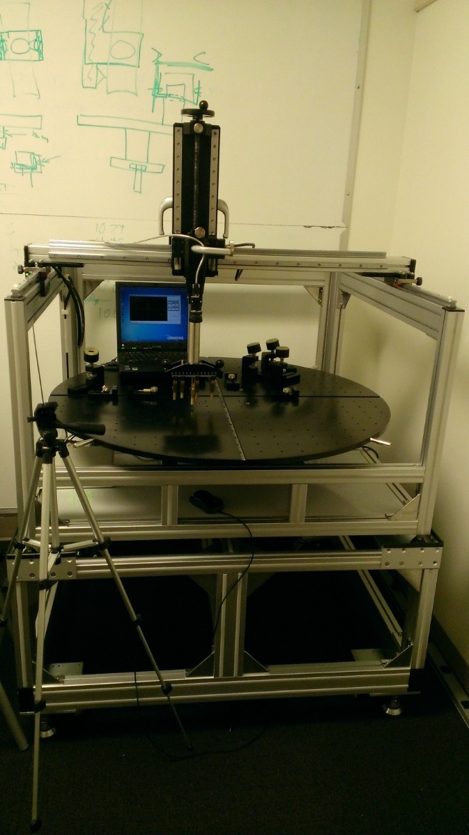
Figure 7: The large PT3 manufactured by ITRI
Installation
Connect X,Y,Z cable from PT3 to the 3-axis display
Connect the USB RS232C cable from 3-axis display to CCD camera cable
Connect USB adapter to computer and install the USB driver
Install the TouchWhere software
Install CCD driver on computer
Calibration
Run the TouchWhere software and touch_all.exe. Verify that in the bottom left corner of the screen, a green dot indicates that the computer is connected to the CCD camera. A red dot indicates that the camera is not communicating with the computer.
On the Configuration tab, enter in the X and Y values from the 3-axis display and the COM port to which the camera is connected.
On the Calibration tab, align the test finger on the PT3 to the green circle shown on the page and click Start point. Do the same for the yellow circle and click End point. Then click Run calibration. When you align the test finger for all tests, move the finger so that the X and Y offsets are as close to 0 as possible.
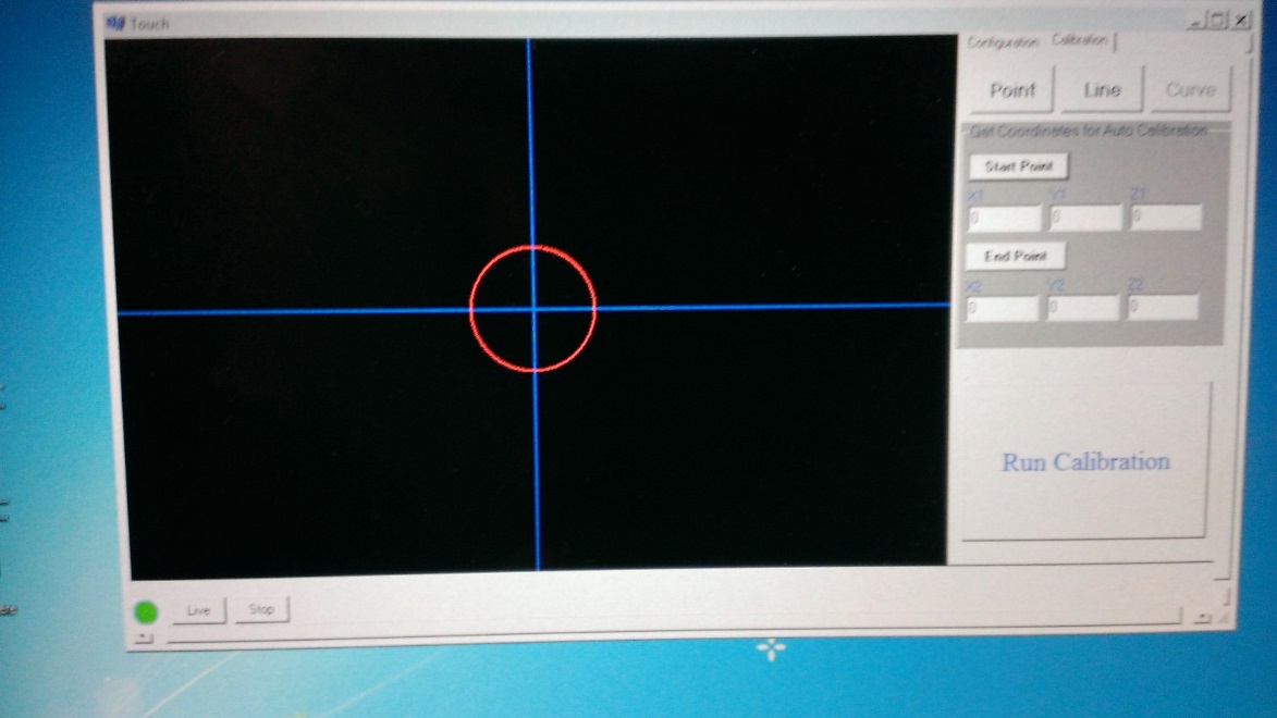
Figure 8: TouchWhere software showing how to calibrate the camera with the DUT
Important
Make sure that the device under test is level when you put it on the base plate of the PT3.