Power Management for Storage Hardware Devices
Introduction
This document is intended as a guide for OEMs and device manufacturers using Microsoft’s in-box SATA and NVMe drivers on Windows 10 May 2019 Update or newer OS versions. Microsoft’s general guidance is to provide in-box solutions that “just work” in terms of balancing performance, responsiveness, and power efficiency. As is the case with overall system performance, poorly-behaved device hardware may compromise overall efficiency and battery life. In general, the system attempts to balance power efficiency with performance.
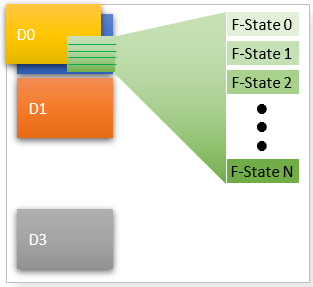
The diagram below illustrates ACPI-defined device power states D0 (working) to D3 (off). Note that as the device transitions into deeper power states, power consumption is reduced, but latency increases. Also note that Windows supports varying functional states (F-States), which can be used to control fine-grained levels functionality and power within the D0 state. This can be useful for runtime power management where the system needs to remain highly responsive, but still needs to save power.

ACPI-Defined Sleep State Power Management
When the system is not in use, Windows may opportunistically place the system in an ACPI-defined sleep state to conserve energy. Likewise, Windows may choose deep sleep states over time to conserve even more power. For example, the system may transition to S3 for a period, and eventually transition to S4 Hibernate. When the system transitions to a sleep state, the general rule of thumb is to place the device in the deepest possible D-state, unless the device is wake-capable, and is armed for wake. Under these conditions, a shallower D-state may be appropriate. Likewise, when the system wakes, the device will transition back to D0.
Runtime Power Management
In order to achieve maximum power efficiency, some components will implement very fine-grained idle logic to determine when devices can be powered down, even when the system is in active use. E.g., a high-end storage device could disable certain functional blocks during runtime if the driver deems that they haven’t been used for some period of time. This is only possible if those functional blocks can be brought back online and made functional quickly enough such that the user does not incur noticeable latencies.
Modern Standby Power Management
When the system is not in use, Windows may opportunistically turn off power to some set of devices to conserve energy. In Modern Standby, the system remains in S0. Even while in S0, all peripheral devices may eventually be powered down due to idle timeouts. This state is defined as “S0 Low Power Idle”. Once all devices are in a low-power state, even more of the system infrastructure (e.g. busses, timers, …) may be powered down. The general rule of thumb is to place the device in the deepest possible D-state when it is idle, even when the system state is S0. Depending on implementation details of the processor complex and platform design, peripheral devices may be required to go to an F-state, D3 Hot, or D3 Cold (power is cut). To mitigate the need for a function driver to manage these implementation details, drivers should go to the deepest appropriate device state in order to maximize battery life.
D3 Support
When the system is not in use, Windows may opportunistically turn off power to some set of devices to conserve energy. In Modern Standby, the system remains in S0. Even while in S0, all peripheral devices may eventually be powered down due to idle timeouts. This state is defined as “S0 Low Power Idle”. Once all devices are in a low-power state, even more of the system infrastructure (e.g. busses, timers, …) may be powered down. The general rule of thumb is to place the device in the deepest possible D-state when it is idle, even when the system state is S0. Depending on implementation details of the processor complex and platform design, peripheral devices may be required to go to an F-state, D3 Hot, or D3 Cold (power is cut). To mitigate the need for a function driver to manage these implementation details, drivers should go to the deepest appropriate device state in order to maximize battery life.
ASL Copy
Name (_DSD, Package () {

          ToUUID("5025030F-842F-4AB4-A561-99A5189762D0"),

            Package () {

                Package (2) {"StorageD3Enable", 1}, // 1 - Enable; 0 - Disable

            }
        }
 )
The ACPI _DSD above is the preferred way to opt into or out of D3 support for storage devices. However, there is also a global registry key that can be used to modify D3 support if needed.
- Name: StorageD3InModernStandby
- Type: REG_DWORD
- Path: HKEY_LOCAL_MACHINE\SYSTEM\CurrentControlSet\Control\Storage\
- Value:
- 0 – Disable D3 support
- 1 – Enable D3 support
If the registry key is not configured, then Storport will check the _DSD configuration to determine whether to enable D3. If the _DSD is not implemented, then Storport will check whether the platform is on the allowlist for D3 support.
Parent/Child Relationship for Power Management
During power-up, the parent/child relationship is always enforced for storage devices. During power-down, the only case where the parent/child power relationship is not enforced is if the controller only supports D3Hot, and the device reports F1 to PoFx (i.e. DEVSLP is supported or it is an SSD in a Modern Standby system), then the controller is allowed to enter D3 while the device is in F1.
In this section
| Topic | Description |
|---|---|
This topic covers power management guidelines for NVMe storage devices. |
|
This topic covers power management guidelines for SATA/AHCI storage devices. |