Using Visio 2010 BPMN to Design, Model and Document BizTalk Solutions
Why do we need to standardize? How we design and model BizTalk Solutions?
- Ideally, one formal description of business processes.
- Understandable by all team members.
- A tool for collaboration between business and IT.
Traditional design and modeling methodology does not work for BizTalk
- Different types of documentation are required to describe the business process.
- Standard Workflow diagrams only provide a high level view.
- Written documentation is required to describe the workflow.
- UML does not support Business Process Design.
- Multiple sets of documents are needed:
- Technical
- Non-technical
Introduction to Business Process Modeling Notation 1.2
The BPMN modeling procedure
Its purpose is:
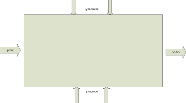
- To analyze a building block (what it is supposed to do).
- To synthesize its implementation (how it does this) as the explicit coordination of other building blocks (processes or activities).
- It is iterative – we can apply it until we have left only indivisible building blocks (i.e. activities).
- Artifacts are constructed recursive.
Principles Of The Modeling Procedure
- It treats human and automated activities equally.
- It is primarily for capturing the flow of control, and not for optimization.
- It is a tool for both the business and the IT.
- It provides validation by simulation.
- It provides validation by quick prototyping – real services can be invoked.
- It is a visual programming approach.
BPMN Basic Elements
| Token |  |
- The behaviors of the Business Process Patterns are best described by using a conceptual “Token”.
- The “Token” is used to demonstrate the sequence flow in a BPMN Diagram.
BPMN Basic Set Shapes
Three kinds of flow objects
| Activity | |
| Gateway |  |
| Event |
Three ways of connecting
| Sequence flow |
|
| Message flow | |
| Association |
Two types of container
| Pools |  |
| Lanes (swimlanes) |
Connectors
- Flow connector represents the sequence of activities within the same pool
- Message connection represents the communication between activities in separate pools
Artifacts
- Annotation: Used to provide the model/diagram with understandable details
- Data object: Show the data is required or produced in an activity
- Group: Used to group different activities but does not affect the flow in the diagram
Coordination Logic
Three types of coordination logic
- **Template-based **
- Static connection of “flow objects” or sequence relationship (predecessor and successor).
- Similar to a river (upstream and downstream).
- Process template is an abstract description of a process.
- Token-based
- Token marks elements which active at a particular time.
- Dynamic connection of “flow objects” or synchronization (wait for) / chronologic relationship.
- Similar to a “flock” of birds (split and join)
- Several tokens may co-exist
- **Instance-based **
- Process instance is an enactment of a process template.
- Each instance may have different behavior of tokens.
- A process instance is completed when all tokens have been consumed.
- A process instance may start several instances of another process
(although the latter is mentioned only once in the former).
Event types
- Start Event: produces a token
- End (or finish) event: consumes a token
- Intermediate token: Means that something happened within a business process engine
Full set of events
Event details
- Classification
- Catching is triggered by an outside event.
- Throwing generates an output.
- Types
- Start Event acts as a trigger for the process.
- End Event represents the end of a process.
- Intermediate Event represents something happens between the Start and End Events.
Processes
Simplest useful process
- It has at least one activity!
Gateways
Parallel gateway
- Activity02, Activity03 and Activity04 will be executed in parallel;
The process will only be continued when each of them is completed
Exclusive gateway
- A single activity Activity02 or Activity03 or Activity04 will be executed.
The choice is based on the logic defined within the gateway G01
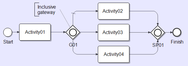
Inclusive gateway
- Several activities can be executed in parallel.
- It covers functionality of parallel and exclusive gateways.
- Logic of tokens is used.
Activities
Logic of templates vs. logic of tokens
- Many tokens can pass the same activity
Process fragments
- Process fragment is a compound activity
- Also called “sub-process
Repeatable process fragments
- Repeating conditions may be different in different systems
- Be explicit within fragments; the exclusive gateway G01 which is used to specify two branches – one to continue the loop and one to exit it
Process fragment as logical grouping
- Catching errors and time-outs
Message Handling
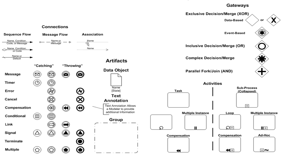
The Full Set Of BPMN Elements
Modeling methodology
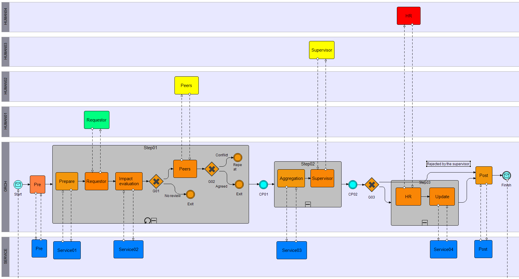
Diagramming style in BPMN
- Horizontal vs. vertical timeline
The Four phases of BPMN Modeling
Blackboxing phase
- The purpose
- To analyze a building block as a whole.
- To discover its functional characteristics and some related artifacts.
- The method
- The business story behind this building block should be carefully analyzed to determine some of its artifacts.
- Recommendations
- At this point, don’t go into excessive detail for each artifact;
This should be done later
- At this point, don’t go into excessive detail for each artifact;
Structuring phases
- The purpose
- To analyze a building block from within to determine its internal structure and its major artefacts
- The method
- Determine the main functional (or logical) steps
- Add check-points between steps
- Classify artifacts for these steps
- Recommendations
- Don’t have more than 7 steps
- Avoid loop-back over check-points
- Steps and check points
- Steps, check points and artifacts
Re-construction phase
- The purpose
- To synthesize an initial version of the formal coordination: some kind of process skeleton
- The method
- Add intra-step logic
- Start formalizing the business objects involved
- Collect test scenarios
- Recommendations
- Consider implementation of human activities as interactive forms
Instrumentation phase
- The purpose
- To enrich the process skeleton by adding more automated activities
- The method
- Add pools
- Apply different practical patterns
- Use a business rule
- Collect test scenarios
- Recommendations
- Work iteratively (step-by-step)
BPMN and BizTalk
How BPMN Shapes and Attributes relate to BizTalk Artifacts
- Each BPMN Shape has a standard set of attributes.
- Each BPMN Shape has specific attributes which directly relate to BizTalk Artifacts.
- Orchestration shapes
- Schemas
- Maps
- BRE Policy and Rules
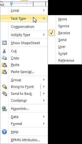
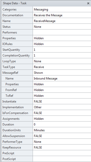
The following example shows the BPMN Attributes for a Task Shape.
- The Task Type is “Receive”.
- The Activity could correspond to a Receive Message Shape in an Orchestration as shown below.
 |
 |
Using Visio 2010 Premium to model a BizTalk Solution
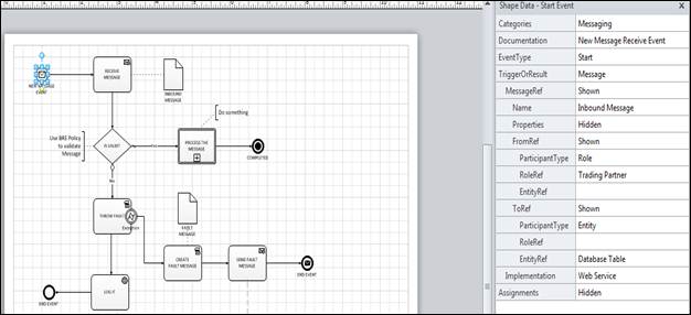
From the BPMN Basic Shapes, drag a “Start Event” shape onto the page.
“Right click” on the “Start Event” shape and click on “BPMN Attributes”.
Position the “Shape Data” window as shown in the example below.
From the BPMN Basic Shapes, drag a “Start Event” shape onto the page.
“Right click” on the “Start Event” shape and click on “BPMN Attributes”.
Position the “Shape Data” window as shown in the example below
The Visio 2010 “Process Menu”
Checking the Diagram
- When you “click” on the “Check Diagram” in the menu, all the pages in your documentary validated against the “built-in” BPMN Validation Rules.
- If the “Issues Window” item is checked, you will see the "Issues Window” as shown in the sample below.
- If the diagram fails validation you are presented with the error information as shown in the sample below
- “Double Clicking” on the line will highlight the shape where the issue occurs within the diagram.
Subprocess Menu Items
Link to Existing
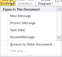
- If you select a shape on your drawing and then “click” on the “Link to Existing” menu item, you are presented with a drop down menu as show below.
You can create a “hyperlink” from the selected shape to any page within the document.
- If you select “Browse to Other Document”, you can also create a “hyperlink” to any file type.
This can be an Excel Mapping document, Message Schema, Message sample, Business Rule Document, etc.
Create New
If you select a “Sub-Process” shape in the diagram and select “Create New” in the menu, a new diagram page is created.
- The page is named from the shape.
- A hyperlink is created from the selected shape to the new page.
Create from Selection
If you select a group of elements on a page and select “Create from Selection”.
 |
 |
A new shape is added to replace the shapes moved to the new page.
This will create a new “Sub-process” Page* as shown below.
Note that the page name is not labeled for the sub-process
Custom BPMN Attributes
Adding Custom Attributes to your Visio BPMN Shapes
Right click on the Shape
Select “Data”, “Define Shape Data”
Click on the “New” Button.
Enter the Label value.
Enter a Name value.
Enter the custom attribute value.
Click “OK”.
Your custom attribute has been added to the Shape Data as shown below.
References
Requirements
- Visio 2010 Premium Edition or Visio 2013 Pro
See Also
Read suggested related topics:
Another important place to find a huge amount of BizTalk related articles is the TechNet Wiki itself. The best entry point is BizTalk Server Resources on the TechNet Wiki.


