Visual Studio 2010: How to understand the domain using UML designers
Visual Studio 2010 can help you understand your problem domain so that you are more likely to solve the right problem. An excellent tool to accomplish this understanding is UML (Unified Modeling Language). The standard notation of UML is an effective way to share diagrams among project stakeholders and ensure that everyone is on the same page with what is being built.
In Visual Studio 2010 Ultimate, there is support for 5 UML diagrams, based on the UML 2.x specs:
- Class diagram
- Sequence diagram
- Use case diagram
- Activity diagram
- Component diagram
There are two additional diagrams that didn’t make it into the product, but are on the backlog: state diagrams and deployment diagrams.
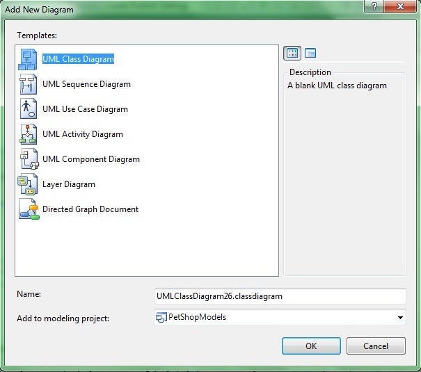
Let’s look at how to create one of these UML diagrams. Click on the “Architecture” menu item in Visual Studio, and then select “New Diagram”. It will bring up this dialog box:
There are the five UML diagrams that we can choose from. Note that these diagrams have to live inside of a modeling project. The dropdown menu at the bottom allows you to either add this new diagram to an existing modeling project in your solution, or create a new modeling project.
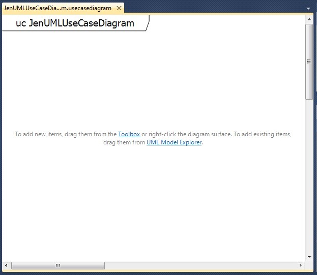
I’m going to create a UML Use Case Diagram. Visual Studio will display a design surface that looks like this:
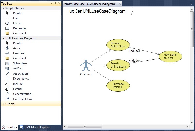
Now I can drag and drop items from the Toolbox and the UML Model Explorer (more on that in a sec). From the Toolbox, I’m going to drag an actor to represent my customer and some use cases.
If you’ve used UML modeling tools in the past, this will be a familiar experience in the Visual Studio environment. The items that you see in the Toolbox are standard UML terminology. However, the thing that makes our UML solution stand out is the integration with TFS and your development process. You can right-click on a use case and select “Create Work Item” and choose the appropriate type (this might be a “User Story” if you are using the agile template or a “Requirement” if you are using the CMMI template in TFS, but you can also link a “Task”, “Bug”, “Issue”, etc. from here). In addition to creating new work items based on these use cases, you can also link to existing work items. This makes it really easy to see how much work is associated with a particular use case. With that information, you can make smart decisions on how many use cases to take on in a particular milestone, or how to load-balance the work across a team.
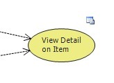
Once I assign work items to the use case, a glyph appears to the upper right of the use case in the diagram.
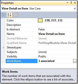
The glyph associated with the use case is shown in the diagram so that you know it has work items associated with it, and how many work items there are. Knowing how many work items are associated with a requirement gives you a sense for how much work would have to be done if the requirement changed. When you click on the glyph, the Properties window will be displayed, which contains a “Work Items” property that specifies how many work items are associated with the use case. Select the “Work Items” property and an ellipsis (…) will appear.
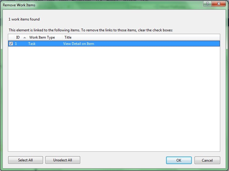
When I click on the ellipsis, I see the actual work items associated with my use case. You can remove the association on this screen as well.
To explore your UML models, you can use the UML Model Explorer. The UML Model Explorer is a logical view of the model repository contained by the modeling project; it represents data that can be displayed across numerous diagrams. It can be accessed by clicking the “Architecture” menu item in Visual Studio, and then selecting “Windows” and “UML Model Explorer”. Cameron Skinner did a post on the UML Model Explorer awhile back that does a great job of explaining its purpose.
Finally, I want to briefly discuss code generation. Starting in Visual Studio 2005, there has been a class diagram that was round-trip…changes to the diagram would change code and vice versa. The Visual Studio team found that some people want to design without generating code until they were ready for it, and that’s what they focused on. So none of these new UML diagrams in VS2010 generate code. However, for those who want code generation:
- You can still create round-trip class diagrams like you could in previous versions of Visual Studio (right-click on the project, select “Add”, “New Item”, and choose the “Class Diagram”). This is completely different from the UML Class Diagram above, and the codebases are still completely separate. There are plans to merge them in the future.
- Cameron Skinner gave us a “sneak peek” at the Feature Pack that is coming soon; watch his blog for the release announcement. One of the features is code generation from the UML Class Diagram.
In summary, UML is a great tool with standardized notation for modeling your problem domain. In Visual Studio 2010, you can leverage UML to design and model your system, and integrate with TFS as a work item tracking system to gain even more knowledge around your development process. In tomorrow’s final post on the architecture functionality in VS2010, I’ll talk about extensibility.
