Use UML Sequence Diagrams in Team System 2010 to reverse engineer your code
One of the new features that we have added in Visual Studio Team System 2010 is the ability to create a new UML Sequence Diagram as well as generate one from existing code. I'm not going to go into too much detail on what a UML sequence diagram is since there is a plethora of information about the subject on Wikipedia. Instead, I'm going to walk you through an example on how to generate a sequence diagram for an existing application using Team System 2010.
For this example, I'm going to use the BeerHouse sample application. BeerHouse contains a method (AddShoppingCartItem) which adds a product to the user's shopping code. The AddShoppingCartItem method is shown below.
 public ActionResult AddShoppingCartItem(int productId, int? quantity)
{
    TheBeerHouseDataContext dc = new TheBeerHouseDataContext();
    ProfileBase profileBase = HttpContext.Profile as ProfileBase;
    ShoppingCart shoppingCart = (ShoppingCart)profileBase.GetPropertyValue("ShoppingCart");

    if (shoppingCart == null)
    {
        shoppingCart = new ShoppingCart();

        // get the cheapest shipping method for our user
        var cheapestShippingMethod = dc.ShippingMethods.GetShippingMethods().Cheapest();
        shoppingCart.ShippingMethod = cheapestShippingMethod;

        profileBase.SetPropertyValue("ShoppingCart", shoppingCart);
    }

    Product product = dc.Products.GetProduct(productId);

    // throw a 404 Not Found if the requested forum is not in the database
    if (product == null)
        throw new HttpException(404, "The product could not be found.");

    ShoppingCartItem item = new ShoppingCartItem(product) {
        Quantity = quantity ?? 1
    };

    shoppingCart.Add(item);

    return RedirectToAction("ViewShoppingCart");
}
You can certainly read through the code above to try and understand what it does. Alternatively, using a UML sequence diagram, you can visually see the sequence of calls within this method. To generate a sequence diagram, right-click anywhere inside the method (in this case AddShoppingCartItem) and select the "Generate Sequence Diagram" method, as shown below.

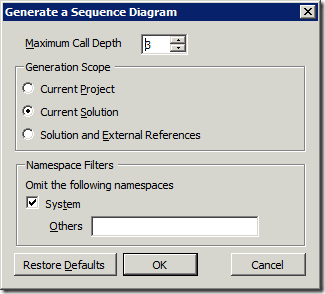
After selecting the Generate Sequence Diagram command, the "Generate a Sequence Diagram" dialog appears, as shown below. The purpose of this dialog is to allow you to control the amount of information that is displayed on the diagram. There are essentially three knobs to control the amount of information that is generated on the diagram: call depth, scope, namespace.

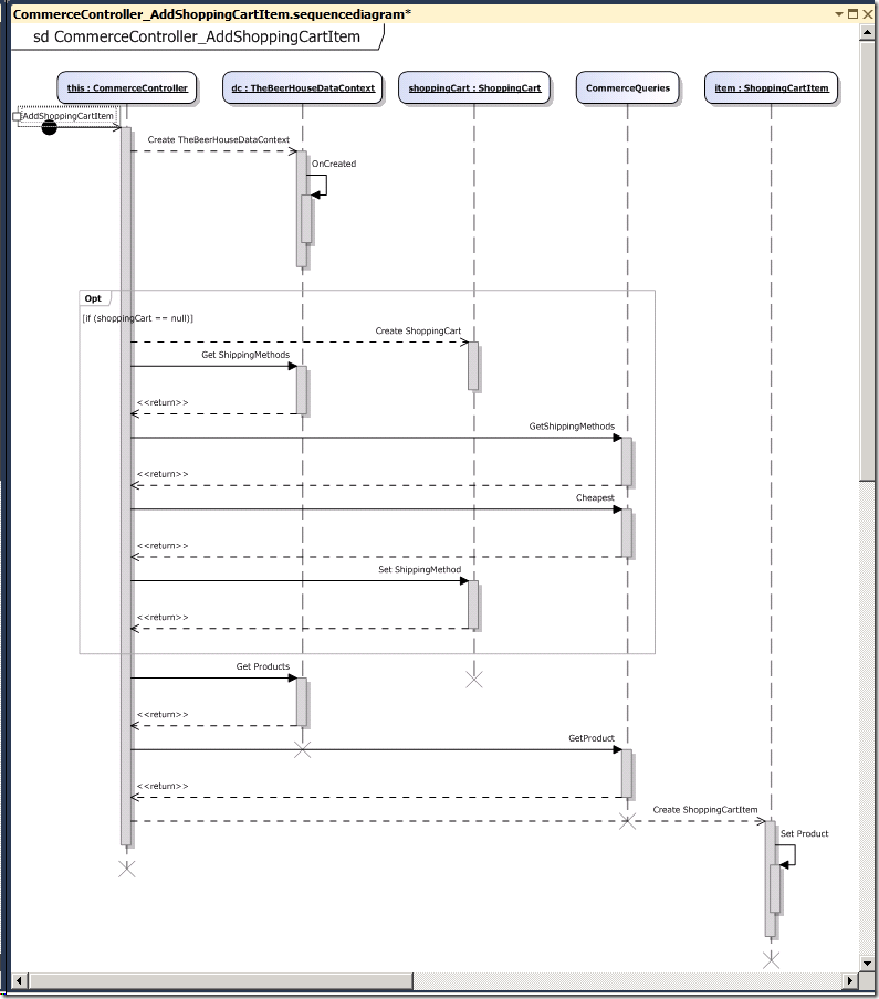
After clicking the [OK] button, the sequence diagram below is generated. It should be immediately clear how much easier it is to understand the sequence of method calls using the diagram instead of reading through the code.
In the diagram below, you can see that there are five objects involved and how the objects interact with each other. Also, there is a section marked Opt which stands for "optional" meaning that the sequence of calls within the Opt section are dependent on some condition being true (in this case when shoppingCart == null).

Tips
Here are a few tips for using sequence diagrams.
Changing the default name of a sequence diagram
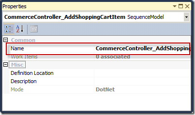
By default, the name of the sequence diagram that is generated is cryptic and not very friendly. You cannot change the name on the diagram itself. Instead, you have to use the Properties window to change the Name property, as shown below.

Adding a comment to a sequence diagram
It's often helpful to annotate sequence diagrams by adding comments. To add a comment, right-click on the sequence diagram and select Add –> Comment.

As a last note, the ability to generate a UML sequence diagram is only supported for C# and VB.NET.
Habib Heydarian.