Best practices for converting and optimizing real-time 3D objects for use in Dynamics 365 Guides or in mixed-reality components included in apps created with Power Apps
This topic covers best practices for converting and optimizing 3D objects to work with Dynamics 365 Guides and for apps created in Power Apps that include mixed-reality components.
Reduce materials and surfacing
Depending on the 3D object source and how you want to present the content, you might want to use the full capabilities of a physically based rendering (PBR) system. PBR systems allow for colors, roughness, and bumpiness to be visually represented by creating texture maps as opposed to having a multitude of different materials and surface complexities in the 3D object.
If the asset just needs to be present and does not need the details provided by a PBR system, a significant increase in performance can be gained by applying only a single color. This leaves out extra texture data and surface information, like multiple colors, reflections, and bumpiness.
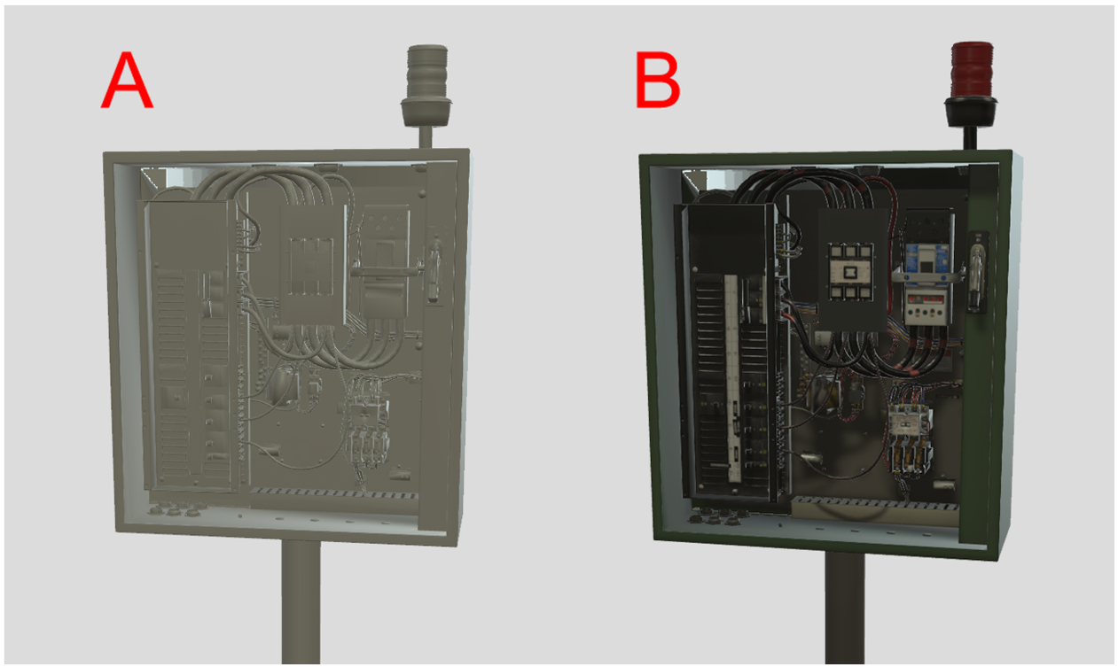
A. High performance single color 3D object with no PBR system
B. 3D object using the PBR system for higher-quality representation
Reduce textures
Decrease the roughness map to increase the performance of the model.
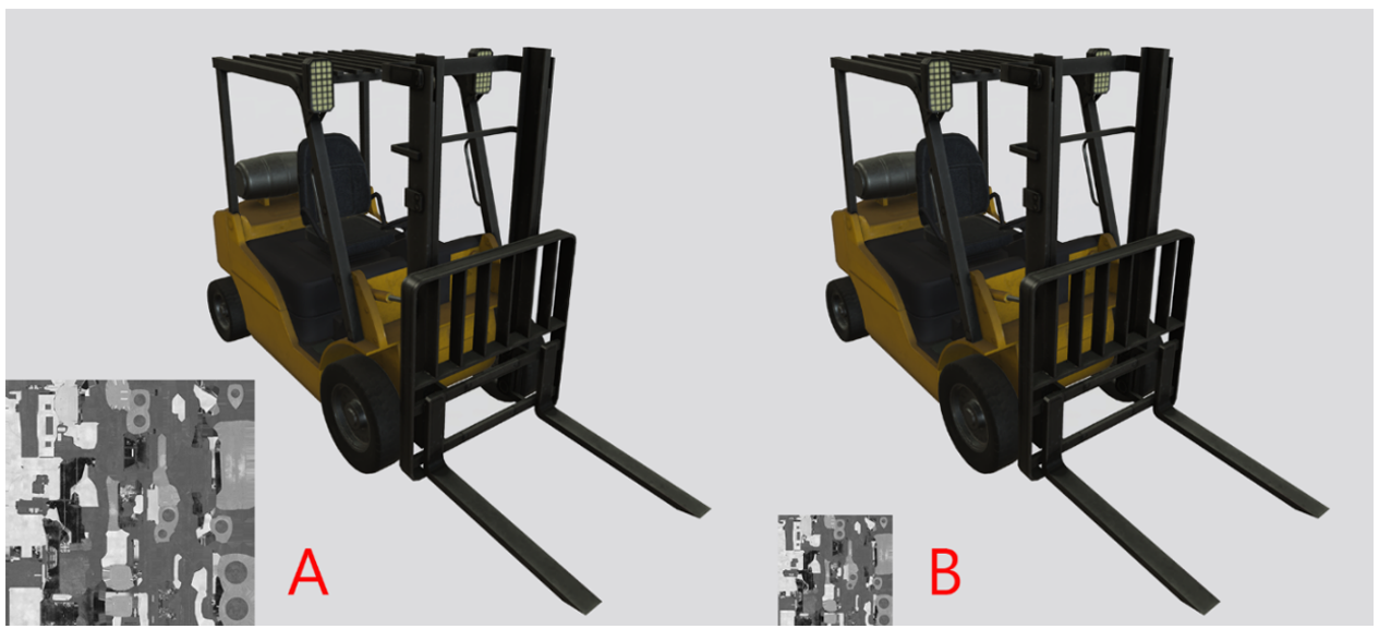
A. Model with roughness map texture of 2048 x 2048
B. Model with roughness map texture of 1024 x 1024Reduce the resolution and the amount of textures to have the largest impact on memory consumption and file size.
Reduce textures based on their visual impact. For example, metallic roughness maps can often be half the resolution of the base color and normal maps with no discernible quality reduction.
JPG compression and PNG quantization further reduce file size, but they have no impact on the memory required at runtime when the model is loaded.
Remove hidden and unused data
Be sure to remove any data that’s not required to represent your 3D objects. Extra nodes, meshes, materials, and textures can add up quickly. For example, in the following 3D object, removing any hidden motor parts lowers the triangle count and simplifies the hierarchy, resulting in a better performing 3D object.
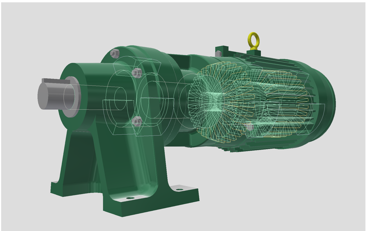
Wireframe and shaded model visualized in Autodesk Inventor.
Reduce triangles
High triangle or vertex counts can hinder performance, especially on performance-constrained devices.
If the model usage is known ahead of time, you can make triangle reduction choices. Focus your reduction on less important areas with high mesh density to allow more detail in key areas.
Fine geometric surface details and material colors can often be replaced by baking them into normal, color, and ORM (occlusion, roughness, and metallic) maps for large triangle savings.
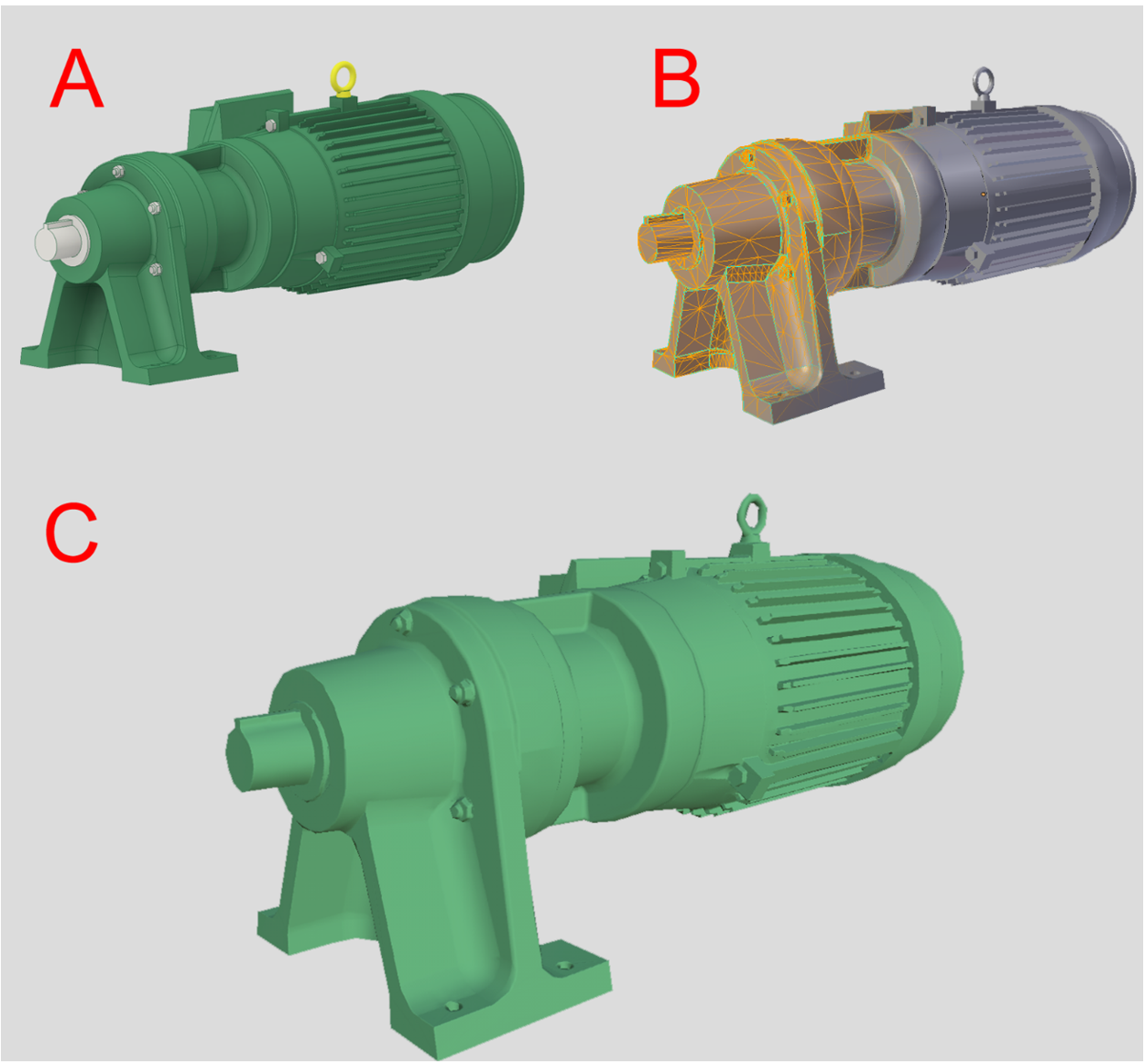
A. Native CAD 3D object
B. Reduced triangle count polygonal model with normal map
C. Optimized model with normal map
Reduce draw calls
Draw calls refers to the number of graphical instructions per frame, which is the number of materials on screen. Reducing or consolidating materials on an object helps reduce draw calls.
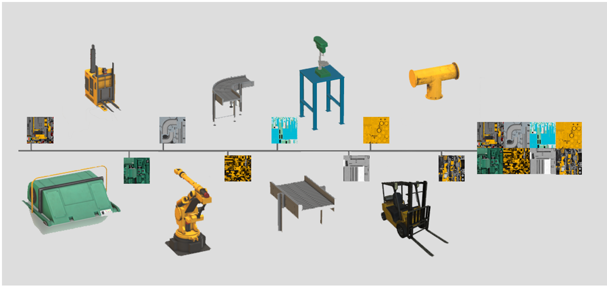
Consolidating multiple textures into a single texture reduces draw calls from 22 to 1 in this example.
The most common runtime performance bottlenecks can usually be attributed to a large number of draw calls.
Create a texture atlas out of multiple materials, and merge the meshes together to consolidate draw calls.
Reduce hierarchy complexity
Grouping, parenting, and large numbers of nodes such as nulls, locators, raw curves, meshes, and joints can contribute to poor runtime performance.
Simplify your hierarchy, remove unnecessary nodes, and combine meshes where possible.
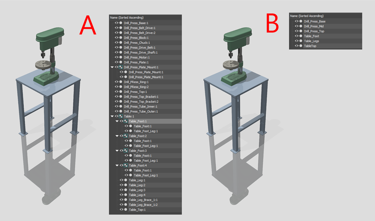
Meshes combined to reduce draw calls. Visualized in Autodesk 3DS Max.
A. Original hierarchy
B. Optimized hierarchyglTF will create one mesh per material and atlas materials together to reduce node count and draw calls.
Increase distance between geometry faces
Flickering can occur when geometry faces are coplanar or nearly coplanar and is especially prevalent when the model is animated or moving from position to position in applications. This means the geometric faces are perfectly overlapping, causing what’s known as Z-fighting.
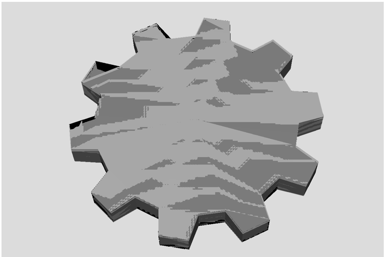
Two shapes are nearly overlapping, causing the Z-fighting effect.
Increasing the distance between geometry faces by a small amount resolves the flickering issues in most cases.
Flip inverted face normals
Inverted face normals can cause the model to be shaded incorrectly.
Flip the normals of the incorrectly shaded faces to resolve the rendering issues.
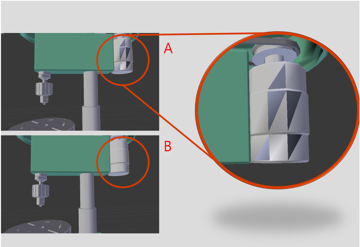
Face normals visualized in Blender.
A. 3D object with normal flipped
B. 3D object with fixed normal
Conflicting tangent basis
A conflicting tangent basis can cause your normal maps to appear inverted.
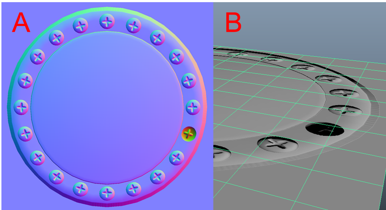
Tangent basis visualized in Autodesk Maya.
A. Normal map baked from a 3D object with a normal-flipped screw
B. The visible result of baking with a flipped normal objectIf you don’t export tangents with your model, glTF and the real-time renderer will assume right-handedness.
Export your model with tangents if you are baking tangent space normal maps in a left-handed setup. Alternatively, you could invert the green channel (Y axis) of your normal map.