Cel Shading in XNA
Ever wondered how games achieve that really cool cartoony looking effect? With the bold, blocky lighting and the big black borders? It’s quite a neat look and helps make games look really eye-catching! It’s easier and more effective to make a game look stylized, than to make a game look extremely realistic! This article will introduce you to the High Level Shader Language (HLSL) and show you how to implement a fully working Cel Shader in XNA.
Getting Started
So in order to get started, you’ll need to have XNA Game Studio installed. It also helps if you have a model to test this on – you can find some models in the starter kits over at https://creators.xna.com
Go ahead and open up Visual Studio and start a new XNA project.
Introduction to the HLSL
The High Level Shader Language (HLSL) is a shading language for use with the Direct3D API. This means it’s not just used in XNA Game Studio but for Direct3D shaders in general. It has 3 main areas: vertex shader, geometry shader and pixel shader.
So let’s add our Cel Shading code. Right-click Content in the Solution Explorer and then add two new folders. One called Effects, one called Models. Right-click the Effects folder and select Add -> New Item…. Select the Effect File option and name it CelShader.fx
Editing the Effect File
Now we have our shader file, if you open it, you’ll notice lots of code already there. This has a basic technique called Technique1. We don’t need that right now, so just delete it all. We need to add some basic variables that our shader will make use of, such as the camera variables (world, view and projection matrices), light direction (vector3). So add the following to your new effect file:
float4x4 world;
float4x4 view;
float4x4 projection;
float3 lightDirection = normalize(float3(1, 1, 1));
Now we have our basic variables, we need to add some variables specific to our cel shader. These help manage the banded lighting on the models.
float toonThresholds[2] = { 0.8, 0.4 };
float toonBrightnessLevels[3] = { 1.3, 0.9, 0.5 };
We also need a variable to store whether or not texturing is enabled, along with the texture being applied and a Sampler. So lets add that now.
bool textureEnabled;
texture Texture;
sampler Sampler = sampler_state
{
Texture = (Texture);
MinFilter = Linear;
MagFilter = Linear;
MipFilter = Linear;
AddressU = Wrap;
AddressV = Wrap;
};
The sampler helps us read the texture that is being stored in our texture variable.
Now that we have our initial variables set up, we need to construct some structs to hold some data for our inputs / outputs. These will hold the position, texture co-ordinates, the normal of the texture and the amount of light.
struct VertexShaderInput
{
float4 Position : POSITION0;
float3 Normal : NORMAL0;
float2 TextureCoordinate : TEXCOORD0;
};
struct LightingPixelShaderInput
{
float2 TextureCoordinate : TEXCOORD0;
float LightAmount : TEXCOORD1;
};
struct LightingVertexShaderOutput
{
float4 Position : POSITION0;
float2 TextureCoordinate : TEXCOORD0;
float LightAmount : TEXCOORD1;
};
struct NormalDepthVertexShaderOutput
{
float4 Position : POSITION0;
float4 Color : COLOR0;
};
Now that we have our structures, we can start creating our functions that will enable us to create some cool effects (in our case, cel shading). So lets create a function that allows us to create the banded lighting effect on our model.
LightingVertexShaderOutput LightingVertexShader(VertexShaderInput input)
{
LightingVertexShaderOutput output;
output.Position = mul(mul(mul(input.Position, world), view), projection);
output.TextureCoordinate = input.TextureCoordinate;
float3 worldNormal = mul(input.Normal, world);
output.LightAmount = dot(worldNormal, lightDirection);
return output;
}
As you can see, this function is using the structures we setup earlier. It uses the variables we initially setup for world, view and projection to get the idea of where the camera is so that the correct matrices are being used before we start applying light. Otherwise, the light direction would be stuck on top of the camera. We then use the dot product to find out the amount of light that is hitting that vertex by using the worldNormal and the lightDirection.
Now we have our vertex shader, let’s create our toon shader to give it that blocky lighting effect. The way cel shading works best, is when it only has 1 or 2 bands of shading. So there’s no gradient effect, but rather just big chunks of shading, like you see in regular cartoons. So if a light value falls within a particular range, let’s just use one value instead of the normal light value. This is specified in the variables we declared above (toonThresholds and toonBrightnessLevels).
float4 ToonPixelShader(LightingPixelShaderInput input) : COLOR0
{
float4 color = TextureEnabled ? tex2D(Sampler, input.TextureCoordinate) : 0;
float light;
if (input.LightAmount > toonThresholds[0])
light = toonBrightnessLevels[0];
else if (input.LightAmount > toonThresholds[1])
light = toonBrightnessLevels[1];
else
light = toonBrightnessLevels[2];
color.rgb *= light;
return color;
}
As you can see in the code, we’re just producing 3 light values all depending upon what value the LightAmount is. This creates that banded lighting effect.
Now that we have our toon shaders, we also need to add some other shaders which we’ll discuss a little more later. These are used to draw the model the first time so that we can enable edge detection (this helps us create the black border.
NormalDepthVertexShaderOutput NormalDepthVertexShader(VertexShaderInput input)
{
NormalDepthVertexShaderOutput output;
// Apply camera matrices to the input position.
output.Position = mul(mul(mul(input.Position, world), view), projection);
float3 worldNormal = mul(input.Normal, world);
// The output color holds the normal, scaled to fit into a 0 to 1 range.
output.Color.rgb = (worldNormal + 1) / 2;
// The output alpha holds the depth, scaled to fit into a 0 to 1 range.
output.Color.a = output.Position.z / output.Position.w;
return output;
}
float4 NormalDepthPixelShader(float4 color : COLOR0) : COLOR0
{
return color;
}
Now that we have all of our shader code for the lighting effects, we can go ahead and create the techniques to use in our code!
technique Toon
{
pass P0
{
VertexShader = compile vs_1_1 LightingVertexShader();
PixelShader = compile ps_2_0 ToonPixelShader();
}
}
technique NormalDepth
{
pass P0
{
VertexShader = compile vs_1_1 NormalDepthVertexShader();
PixelShader = compile ps_1_1 NormalDepthPixelShader();
}
}
There we have our lighting code! That’s great, but we don’t have our black borders yet. So before we continue, let’s add our Post Process effect (the black borders).
Post Processing Effects
So let’s do the same thing we did before to create an effect file, and call this one PostProcess.fx
Same as the last effect file, delete everything we have there and we’ll start from scratch! We need to add some variables for use in the file, so lets add those now. We need one to control how thick the border will be and how dark the stroke will be:
float edgeWidth = 1;
float edgeIntensity = 1;
float normalSensitivity = 1;
float depthSensitivity = 10;
We also need a variable to store how accurate the edge detection is. The higher the number, the less it will pick up. This is good for getting rid of unwanted edges on really detailed models.
float normalThreshold = 0.5;
float depthThreshold = 0.1;
We also need a variable to store the screen resolution (WxH).
float2 screenResolution;
As with the last effect file, we need to store the texture and create a Sampler – both for the scene (edge detection filter will be written over this) and the normal depth scene.
texture sceneTexture;
sampler SceneSampler : register(s0) = sampler_state
{
Texture = (sceneTexture);
MinFilter = Linear;
MagFilter = Linear;
AddressU = Clamp;
AddressV = Clamp;
};
texture normalDepthTexture;
sampler NormalDepthSampler : register(s1) = sampler_state
{
Texture = (normalDepthTexture);
MinFilter = Linear;
MagFilter = Linear;
AddressU = Clamp;
AddressV = Clamp;
};
Now is a good time to sit and think a bit about how cel shading works. We’re going to render a scene with edge detection, so that we can gather the edges of the models. This allows us to determine where we need to draw the lines. We then map a texture of the scene which gives us an idea about where to draw the line. If it’s an edge, we then add a line (thickness and intensity are determined by our variables above).
float4 PixelShader(float2 texCoord : TEXCOORD0) : COLOR0
{
float3 scene = tex2D(SceneSampler, texCoord);
float2 edgeOffset = edgeWidth / screenResolution;
float4 n1 = tex2D(NormalDepthSampler, texCoord + float2(-1, -1) * edgeOffset);
float4 n2 = tex2D(NormalDepthSampler, texCoord + float2( 1, 1) * edgeOffset);
float4 n3 = tex2D(NormalDepthSampler, texCoord + float2(-1, 1) * edgeOffset);
float4 n4 = tex2D(NormalDepthSampler, texCoord + float2( 1, -1) * edgeOffset);
float4 diagonalDelta = abs(n1 - n2) + abs(n3 - n4);
float normalDelta = dot(diagonalDelta.xyz, 1);
float depthDelta = diagonalDelta.w;
normalDelta = saturate((normalDelta - normalThreshold) * normalSensitivity);
depthDelta = saturate((depthDelta - depthThreshold) * depthSensitivity);
float edgeAmount = saturate(normalDelta + depthDelta) * edgeIntensity;
scene *= (1 - edgeAmount);
return float4(scene, 1);
}
Now we just need to map this function to a technique and we can start implementing these in our XNA game code!
technique EdgeDetect
{
pass P0
{
PixelShader = compile ps_2_0 PixelShader();
}
}
Implementing the Effects in XNA
We’re not done yet! We still need to add these to our code. So let’s do some initialisation and add our content. So add these variables at the top:
Effect celShader;
Effect postProcessEffect;
Model myModel;
RenderTarget2D sceneRenderTarget;
RenderTarget2D normalRenderTarget;
Here, we’re simply declaring our two effect files we’ve already created, our model that we’ll be using and 2 render targets (used for our post process effect – check above).
In the initialization function, add the following code:
celShader = Content.Load<Effect>(@"Effects\CelShader");
postProcessEffect = Content.Load<Effect>(@"Effects\PostProcess");
We also need to initialise our render targets, so add the following code just below the above:
PresentationParameters pp = graphics.GraphicsDevice.PresentationParameters;
normalRenderTarget = new RenderTarget2D(graphics.GraphicsDevice,
pp.BackBufferWidth, pp.BackBufferHeight, 1,
pp.BackBufferFormat, pp.MultiSampleType, pp.MultiSampleQuality);
sceneRenderTarget = new RenderTarget2D(graphics.GraphicsDevice,
pp.BackBufferWidth, pp.BackBufferHeight, 1,
pp.BackBufferFormat, pp.MultiSampleType, pp.MultiSampleQuality);
Now that we’ve initialised out effects and render targets, we need to load in our model. Go to the LoadContent function and add the following line (change the name depending upon your model name):
myModel = Content.Load<Model>(@"Models\Human");
Now we’ve initialised and loaded our content we can start doing stuff with it. However, we need to do some logic on our model before we start rendering. This is so that we can store the textures for our models whilst manipulating effects on it. Add the following function call after you have loaded your model:
ChangeEffectUsedByModel(myModel, celShader);
Now for the actual function – declare this function as follows:
static void ChangeEffectUsedByModel(Model model, Effect replacementEffect)
{
Dictionary<Effect, Effect> effectMapping = new Dictionary<Effect, Effect>();
foreach (ModelMesh mesh in model.Meshes)
{
foreach (BasicEffect oldEffect in mesh.Effects)
{
if (!effectMapping.ContainsKey(oldEffect))
{
Effect newEffect = replacementEffect.Clone( replacementEffect.GraphicsDevice);
newEffect.Parameters["Texture"].SetValue(oldEffect.Texture);
newEffect.Parameters["TextureEnabled"].SetValue( oldEffect.TextureEnabled);
effectMapping.Add(oldEffect, newEffect);
}
}
foreach (ModelMeshPart meshPart in mesh.MeshParts)
{
meshPart.Effect = effectMapping[meshPart.Effect];
}
}
}
Now we can draw the models and apply the post processing effects. As we’re going to be drawing the model more than once, it’s cleaner to create our own DrawModel function. Declare a new DrawModel function:
void DrawModel(Matrix world, Matrix view, Matrix projection,
string effectTechniqueName, Model model)
{
RenderState renderState = graphics.GraphicsDevice.RenderState;
renderState.AlphaBlendEnable = false;
renderState.AlphaTestEnable = false;
renderState.DepthBufferEnable = true;
Matrix[] transforms = new Matrix[model.Bones.Count];
model.CopyAbsoluteBoneTransformsTo(transforms);
foreach (ModelMesh mesh in model.Meshes)
{
foreach (Effect effect in mesh.Effects)
{
effect.CurrentTechnique = effect.Techniques[effectTechniqueName];
Matrix localWorld = transforms[mesh.ParentBone.Index] * world * Matrix.CreateScale(40.0f);
effect.Parameters["world"].SetValue(localWorld);
effect.Parameters["view"].SetValue(view);
effect.Parameters["projection"].SetValue(projection);
}
mesh.Draw();
}
}
Here, we’re drawing the model with the effect technique that we’re passing in. If you remember, we created two techniques in our CelShader, Toon and NormalDepth. Toon does the toon shading, NormalDepth handles the edge detection. We’re also passing in the model, view, world and projection matrices.
Now we have a draw function, we need to add a post process function to handle our post processing. To do this, we pass in our effect technique name (in this case, EdgeDetect) and it then renders the scene texture. So lets declare our post processing function and implement our post processing effect:
void ApplyPostProcess(string effectTechniqueName)
{
EffectParameterCollection parameters = postProcessEffect.Parameters;
Vector2 resolution = new Vector2(sceneRenderTarget.Width,
sceneRenderTarget.Height);
Texture2D normalDepthTexture = normalRenderTarget.GetTexture();
parameters["edgeWidth"].SetValue(1);
parameters["edgeIntensity"].SetValue(1);
parameters["screenResolution"].SetValue(resolution);
parameters["normalDepthTexture"].SetValue(normalDepthTexture);
postProcessEffect.CurrentTechnique = postProcessEffect.Techniques[effectTechniqueName];
spriteBatch.Begin(SpriteBlendMode.None,
SpriteSortMode.Immediate,
SaveStateMode.None);
postProcessEffect.Begin();
postProcessEffect.CurrentTechnique.Passes[0].Begin();
spriteBatch.Draw(sceneRenderTarget.GetTexture(), Vector2.Zero, Color.White);
spriteBatch.End();
postProcessEffect.CurrentTechnique.Passes[0].End();
postProcessEffect.End();
}
As you can see, it’s fairly simple. We’re passing in some parameters for our post processing effect (in this case, edge width, intensity, resolution and the depth texture) and then drawing that effect to the screen.
We’re almost done! Now we have these functions, but they aren’t currently being called. So let’s go to our Draw function and use the functions! First, we need to add some variables and logic around the view, world and projection matrices. These would usually be done by a camera class of some sort, but we’re just going to put some static values that all us to see our model. In the Draw function, add the following code:
Viewport viewport = graphics.GraphicsDevice.Viewport;
float aspectRatio = (float)viewport.Width / (float)viewport.Height;
Matrix rotation = Matrix.CreateRotationY(1.0f);
Matrix view = Matrix.CreateLookAt(new Vector3(3000, 3000, 0),
new Vector3(0, 1500, 0),
Vector3.Up);
Matrix projection = Matrix.CreatePerspectiveFieldOfView(MathHelper.PiOver4, aspectRatio, 1000, 10000);
Now we have our camera set up, we can go ahead and start drawing stuff (finally!) – first, we need to do the normal depth drawing. Add the following code just below the above:
graphics.GraphicsDevice.SetRenderTarget(0, normalRenderTarget);
graphics.GraphicsDevice.Clear(Color.Black);
DrawModel(rotation, view, projection, "NormalDepth", myModel);
Now we need to draw with the toon effect. This is on a different render target, so use the following code:
graphics.GraphicsDevice.SetRenderTarget(0, sceneRenderTarget);
graphics.GraphicsDevice.Clear(Color.CornflowerBlue);
DrawModel(rotation, view, projection, "Toon", myModel);
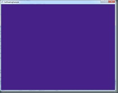
Now we just need to call our post processing effect – if we don’t call our post processing effect, we’ll get this screen:
Which we clearly don’t want! So let’s call that now – underneath the code we just added in our Draw function, add the following:
graphics.GraphicsDevice.SetRenderTarget(0, null);
ApplyPostProcess("EdgeDetect");
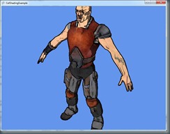
If you compile and run the application now, you should see your model in all it’s cartoony glory!
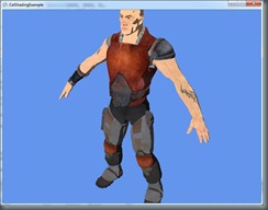
Of course, if you don’t want the lines you can just take out the call DrawModel where we use NormalDepth – that will give you the toon shading like this:
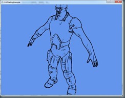
Or – if you just want the lines, you can comment out the call to the Toon effect draw and get this:
Hope this provided decent insight to the HLSL and some cool things that can be done with it! Let us know what cool effects you can come up with!
More information
If you’re looking for more resources, information or help, there’s a great community built up around XNA that you can find over at https://creators.xna.com There’ll you’ll find a whole bunch of starter kits, demos and tutorials to help you out!
