Silverlight3 PlaneProjection Primer
A while ago, I cracked open Silverlight3’s PlaneProjection (aka 3D perspective transform ) feature. Below you should find the basic intro plus all the advanced stuff that had not been documented when I tried to learn it. It is a long read, if you are already an expert, skip to the “3D scene” section to read the interesting details.
The post comes with this application that I used to learn and illustrate the points. Source for the app is here.
Click on the Figures below to go to the respective page on the demo app. SL3 is required! You might need to maximize your screen to see the demos.
Introducing PlaneProjection Silverlight3 introduces a new Projection property on UIElement. The property is of type Projection (an abstract class).
In SL3, the only implementation of Projection class is PlaneProjection, which is an implementation of a 3D PerspectiveTransform. As of SL3 beta1, the implementation is software-based (so not hardware accelerated today).
The UIElement that is projected into this 3D scene is interactive even if projected. Both front and back are interactive.
PlaneProjection = Transforms + 3D scene For me, it is easiest to think of PlaneProjection as a wrapper for a 3D scene and series of 3D Transforms that you can apply to a UIElement to get it to ‘project’ in 3D space.
The transforms that PlaneProjection applies to its UIElement are:
- A TranslateTransform exposed via LocalOffsetX, LocalOffsetY, LocalOffsetZ in PlaneProjection.
- A set of RotateTransform represented by the CenterOfRotationX, CenterOfRotationY and CenterOfRotationZ and the RotationX, RotationY an RotationZ properties.
- A TranslateTransform(3D) , exposed via GlobalOffsetX, GlobalOffsetY, GlobalOffsetZ
Before I get into these transforms, let’s cover the coordinate system.
Silverlight 3D coordinate system
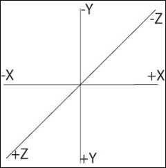
This system is similar to what Silverlight uses in 2D:
+Y increases as you go down the vertical axis,
+X increases as you go to the right.
+Z increases towards the viewer.
Note: WPF uses a different system, called Right hand system, in WPF, the Y increases as you towards the top on the vertical axis.
Figure1. Coordinate System
RotateTransform
A RotateTransform rotates the object around an axis (X,Y,or Z).
You specify the CenterOfRotation (which is normalized, 0 to 1, as a percentage of the actual object size) for the axis, and then you specify the angle in degrees for the Rotation.
On Figure 2, you can see an Image of a duck rotated around the X Axis. You first see the original, and then four rotations at 40, 80, 120, and 160 degrees. All of the rotations are the same for each row, but the second and third row have a different CenterOfRotationY property.
The second row has CenterOfRotationY = 0.1; it rotates near the top of the UIElement (10% from the top).
The third row has CenterOfRotationY = 0.9; so it rotates near the bottom of our UIElement.
While looking at Rotations of 120 and 160 degrees, notice that there is no back material to our object. Silverlight acts as if back was transparent, letting you see the front material but rotated since you are watching from the back.
Figure 2. Rotate Transforms
You may wonder what happens if I stack two objects in say a Canvas, one on front of the other, like this:
<CanvasWidth="300"Height="300">
<Canvas.Projection>
<PlaneProjection RotationX="120"/>
</Canvas.Projection>
<RectangleFill="Red"Width="100"Height="100"/>
<RectangleFill="Black"Width="100"Height="100"/>
</Canvas>
We have a Red rectangle, right behind a Black one? What is the back material now if we rotate the Canvas to see the back?
The back material is still the Black rectangle; it looks like Silverlight projects what is visible on the screen, so you get the back of the Black rectangle.
Rotations can be negative numbers; a rotation of –50 degrees looks like a rotation of 310 degrees; however, if you are animating you will see these animate in opposite directions (and 310 flips a lot more )yet they end up at same spot.
For the most part, that takes care of rotate transforms. The only other thing to notice is that since we are transforming a 2D object on an Axis, the CenterOfRotationY affects RotationX, and the CenterOfRotationX affects the RotationY.
Translate Transforms.
A TranslateTransform simply moves the object by an Offset vector. For example: an object at 1,1,1 with an offset of 50,74,-1 will end up at 51, 75, 0). The units are Silverlight units relative to the screen; more on this below when we cover the 3D scene.
PlaneProjection exposes two translate transforms: A GlobalOffset and a LocalOffset transform:
GlobalOffset transform
The GlobalOffset Transform moves the object relative to the screen’s axis. This means the X,Y,and Z offset are in the coordinate system I showed above in Figure1. Think about it as a translation after the rotation has happened. The object is rotated first, and then after that, the resulting, rotated object is simply moved or translated. This model is similar to what we see in 2D space.
LocalOffset transform
The LocalOffset as a translate transform applied prior to the rotation. We already established that the CenterOfRotation affects the rotation. Consider what happens if we first translate the object and then rotate it around a specific CenterOfRotation, since the translate transform does *not* change the CenterOfRotation, you end up rotating around the axis with the translation applied. That is what a LocalOffset transform does.
Figure 4 on the right shows you what happens with a LocalOffset + Rotation combination applied.
Row1 shows three images in a spot (marked by red border). Each image has a different frame (or border) and a different rotation. Green has RotationY=50; Yellow RotationY=130 (so 180-50). The third image (black border) has no rotation at all.
Notice that since first row has not translate transforms, therefore the rotations are in-place (within the red border).
Row2 shows same images +rotations), but LocalOffsetX=250. The image in the black frame shows where the image is located after the translation; it is 250 units to the right of the red border (on X axis). Notice that the rotation is not in place any more (not within the red borders). In this row, the center of Origin is 0.5, so the images at 50 and 130 rotations are at symmetrical distance from the center of the red border (which is our center of origin, at 0.5).
Row3 has LocalOffsetX=250 and CenterOfOriginX=0.1.
Since 0.1 is < 0.5, our CenterOfRotation is to the left from the one on previous row; since the center of rotation is farther away from the actual image, our rotation is the widest here. The yellow frame is furthest from the red border.
Figure 4. LocalOffset Transforms
The fourth rotation has CenterOfOrigin=0.9, so this time we are moving our CenterOfOrigin closer to where the image was translated to, so our rotation is less wide than it was at both 0.5 and 0.1 .
That should cover the transforms! If you need to play more with this, try the sandbox from the demos page.
Now we get to the other half of PlaneProjection: a 3D scene.
The 3D scene A 3D scene usually consists of a Camera, Lights, a mesh (the shape of your object) and a material (used to “paint” or “cover” your object ). You need to know the Position of the camera (relative to the objects in the scene) and the FieldOfview angle.
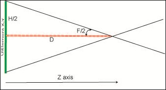
Figure 5 shows the basic elements of a 3D camera placement.
F == field of View (in degrees or radians)
D == distance (on Z plane) from the camera to the XY plane
H == ActualHeight of object in our XY plane
Figure 5. Basic 3D scene
Those are the basics of a 3D scene, let’s now cover the Silverlight 3 specifics:
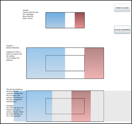
FieldOfView == 57.0 degrees At first, I was slightly concerned that I could not change field of view, but then I noticed that Silverlight does not clip the 3D scene. PlaneProjection works similar to RenderTransform where as you scale your UIElement, you can go over the UIElement’s render bounds (ActualHeight/ActualWidth) and the transform does not affect layout. This means if your container does not clip, then field of view is irrelevant as you are seeing everything regardless.
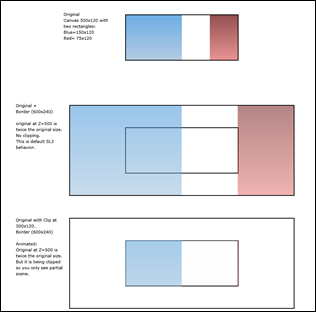
Figure 6 shows Field Of view and clipping interactionRow1: A Canvas with two rectangles inside it. The blue rectangles take half the canvas space and the red rectangle takes 1/3 of the Canvas space.
Row2: With a PlaneProjection with GlobalOffsetZ= 500, the Canvas is a twice its original size. Notice there is no clipping. This is default SL3 behavior, so field of view is fairly irrelevant as you are seeing the whole scene most of the time.
Row 3: Same PlaneProjection applied to original Canvas, but this time the border hosting the original Canvas is clipping at 300x120.. So you only see partial scene. Again this is not default behavior but for those wanting to clip, you know it can be done.
Figure 6. GlobalOffsetZ = 500, 2x.
D = 999
The next thing on the scene is the distance from camera to xy plane. The answer there is a weird 999. The number I am certain, the behavior I am still trying to grasp . Let’s explain:
If D was distance to camera and it was 999, then when you did a GlobalOffsetZ > 999, the object should not be in the scene, but what SL 3D does is allow for Zindex to be > 999 and then it rotates (as if you were looking at the back I assume).
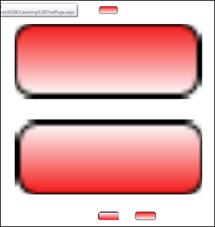
Figure 7 shows:
Row 1: Original object. Rectangle with a gradient. This is very small on purpose (since it is scaled a lot when we increase ZIndex).
Row 2: Same object, but GlobalZIndex = 900. [so 99 away from 999].
Still looking at the front of the rectangel.Row 3: Same object, GlobalZindex = 1098 [so 99 over 999]. Notice that the we are looking at the back of the object. It is the same size than 900.
Row 4: Has two objects.
First object = original + GlobalZIndex = 1899 (900 over 999), notice we are looking at the back of object but it is not scaled much. Second object is Original object + GlobalZIndex = 99. It is same size as GlobalZIndex = 1899 and we are looking at the front.
Figure 7. GlobalZIndex > 999
If you are wondering why when you look at the API for PlaneProjection the default value for GlobalOffsetZ and LocalOffsetZ is 0 and I am saying the camera is at 999, PlaneProjection applies the D = 999 is by moving the object before you get the scene, so the distance to the camera is there, but you don’t see it (or can’t change it) from the API.
What about H? why does it matter?
H is relevant because it tells you where the camera is in relation to the XY plane. Not the distance to it, but where within that plane the camera is located. The short answer is that the camera is at the center. The long answer is that there is some scaling going on to make that happen.
For sizing of our scene, the math would go along H = 2*D*tan (F/2); since both F(57) and D (999) are fixed, then H should also be fixed (1084), but of course our UIElement is not of that same size, so the object is scaled and aspect ratio is maintained.
For the most part, you do not notice this scaling (nor should you care), but if needed you can use this knowledge to accomplish two things:
- Position the camera
- Create a 3D scene where multiple objects of different sizes appear to be in the same scene, with a common camera angle.
Figure 8.
Let’s go back to our earlier example where I showed you a clipped scene, this time the canvas in the last row is 500x120 instead of 300x120. if you see it before changing GlobalOffSetZ, visually it all looks the same.When you animate GlobalOffsetZ, you notice the center of origin of the Projection is farther to the right ( at 250, which is the first third in the rectangle, so our rectangle would no longer clip, part of it is visible.
[I removed the clip on the border so you could see the scene, but it is easy to see that some of the red rectangle is still fitting in the border that was clipping the whole rectangle earlier.
Figure 8 – Canvas to position camera.
The example above is not that exciting or enlightening; you can accomplish some thing similar with a few transforms, so I am not proposing that you change the size of your containers to manipulate the camera, however the trick does come in handy when you have UIElements that are of different sizes but need to “integrate” into a 3D scene; and the UIElements need to be rotated separately. If you are familiar with WPF, this would be like having multiple GeometryModels within a scene; you rotate these independently, but relative to a single camera and lights scene.
Since I explained earlier that camera is located relative to the “center” of each UIElement, there fore getting multiple objects of different sizes to have the camera in the exact same spot is not doable unless we workaround it, and the workaround is to apply a Canvas to wrap each of my UIElements, and size all wrapper canvases to the same size, this way as I rotate them and manipulate them, they all have same relative CenterOfOrigin.
Figure 9 demonstrates this trick.
Row1 shows a canvas with rectangles in it. The rectangles have slightly different sizes.Row2 shows the rectangles translated to GlobalOffsetZ = 500 (twice original size).
Notice that the “top” of the rectangles are not aligned (unless the height of the rectangle was the exact same prior to the transform). I used the redlines to demonstrate the differences after translation.Row 3 translated the canvas instead of the rectangles, notice the top of the rectangles are aligned.
Figure 9. Using same size Canvas to align UIElements
to get same Center of Origin.
OK that covers most of what I found out on Silverlight’s PlaneProjection. I do have a useful sandbox page for playing around with a lot of these concepts.
On the overall 3D API, I think it is quite simple, yet it lets you do a lot.
Comments
Anonymous
June 02, 2009
PingBack from http://asp-net-hosting.simplynetdev.com/silverlight3-planeprojection-primer/Anonymous
June 03, 2009
This is the MISSING LINK. Thanks for clearing this up.
